
Page 1335 - Workshop Manual - Aumark (BJ1051)
P. 1335
61-63
Circuit-System circuit diagram
Service hint
z B025 combined switch
11-2: it is connected when the combined switch is at small lamp position.
z R32 small lamp relay
3-5: the contact will be closed when the combined switch is at the small lamp position.
z B039 lighting, cigar lighter
1-grounding: the voltage is about 24 V when the combined switch is at small lamp position.
2-grounding: it is connected always.
z B040 Cigar lighter
1-grounding: the voltage is about 24V when the ignition switch is at ACC or ON position.
2-grounding: it is connected always.
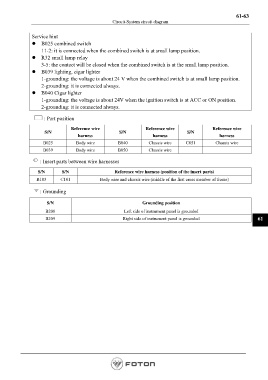
: Part position
Reference wire Reference wire Reference wire
S/N S/N S/N
harness harness harness
B025 Body wire B040 Chassis wire C051 Chassis wire
B039 Body wire B050 Chassis wire
: Insert parts between wire harnesses
S/N S/N Reference wire harness (position of the insert parts)
B103 C101 Body wire and chassis wire (middle of the first cross member of frame)
: Grounding
S/N Grounding position
B208 Left side of instrument panel is grounded
B209 Right side of instrument panel is grounded 61
Page 1335