
Page 1333 - Workshop Manual - Aumark (BJ1051)
P. 1333
61-61
Circuit-System circuit diagram
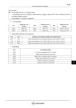
Service hint
z C044 solenoid valve of exhaust brake
1-grounding: turn on the ignition switch and the voltage is about 24V when combined switch is
at exhaust brake position.
2-grounding: it is always connected.
: Part position
Reference wire Reference wire Reference wire
S/N S/N S/N
harness harness harness
B029 Body wire B050 Body wire C033 Chassis rear wire
B034 Body wire C051 Chassis wire C044 Chassis rear wire
: Insert parts between wire harnesses
S/N S/N Reference wire harness (position of the insert parts)
B103 C101 Body wire and chassis wire (middle of the first cross member of frame)
C106 B104 Body wire and chassis wire (middle of the first cross member of frame)
C102 B105 Body wire and chassis wire (middle of the first cross member of frame)
: Grounding
S/N Grounding position
B204 Left side of instrument panel is grounded
B205 Right side of front panel is grounded
A206 Right side of instrument panel is grounded
B207 Right side of front panel is grounded
C237 Chassis wire harness is grounded
C238 Chassis wire harness is grounded 61
Page 1333