Page 1337 - Workshop Manual - Aumark (BJ1051)
P. 1337

61-65
                                                   Circuit-System circuit diagram
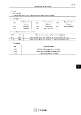
               Service hint
               z   R34 Horn relay
                   3-5: the contacts will be closed when the combined switch is at horn position.

                     : Part position

                                 Reference wire                   Reference wire               Reference wire
                     S/N                              S/N                           S/N
                                    harness                          harness                       harness
                    B025           Body wire         C046          Chassis wire     C051       Wire of right door
                    B050           Body wire         C047        Wire of left door

                   : Insert parts between wire harnesses

                  S/N        S/N                    Reference wire harness (position of the insert parts)
                 B103       C101             Body wire and chassis wire (middle of the first cross member of frame)

                 C105       C105             Body wire and chassis wire (middle of the first cross member of frame)

                   : Grounding

                      S/N                                       Grounding  position
                     B208                               Left side of instrument panel is grounded
                     B208                               Right side of instrument panel is grounded
                     C237                                  Chassis wire harness is grounded


                                                                                                                   61


                                                                                                        Page 1337
   1332   1333   1334   1335   1336   1337   1338   1339   1340   1341   1342