
Page 192 - Workshop Manual - Aumark (BJ1051)
P. 192
04-48
Diagnose- ABS system
No > Replace fuse F23 (15A) and repair line to ground short between the fuse and connector
pin 8 of ABS control unit B013.
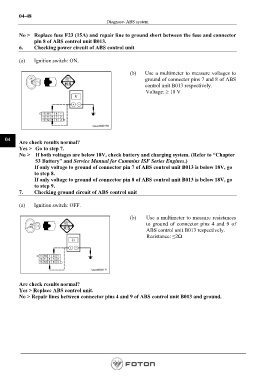
6. Checking power circuit of ABS control unit
(a) Ignition switch: ON.
(b) Use a multimeter to measure voltages to
ground of connector pins 7 and 8 of ABS
control unit B013 respectively.
Voltage: ≥ 18 V
04
Are check results normal?
Yes > Go to step 7.
No > If both voltages are below 18V, check battery and charging system. (Refer to “Chapter
53 Battery” and Service Manual for Cummins ISF Series Engines.)
If only voltage to ground of connector pin 7 of ABS control unit B013 is below 18V, go
to step 8.
If only voltage to ground of connector pin 8 of ABS control unit B013 is below 18V, go
to step 9.
7. Checking ground circuit of ABS control unit
(a) Ignition switch: OFF.
(b) Use a multimeter to measure resistances
to ground of connector pins 4 and 9 of
ABS control unit B013 respectively.
Resistance: ≤2Ω
Are check results normal?
Yes > Replace ABS control unit.
No > Repair lines between connector pins 4 and 9 of ABS control unit B013 and ground.
Page 192