
Page 490 - Workshop Manual - Aumark (BJ1051)
P. 490
04-346
Diagnosis- combination meter
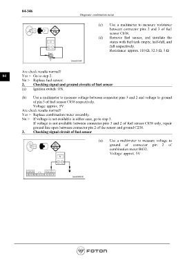
(c) Use a multimeter to measure resistance
between connector pins 2 and 3 of fuel
sensor C038.
(d) Remove fuel sensor, and simulate the
states with fuel tank empty, half-full, and
full respectively.
Resistance: approx. 110 Ω, 32.5 Ω, 3 Ω
Are check results normal?
04 Yes > Go to step 2.
No > Replace fuel sensor.
2. Checking signal and ground circuits of fuel sensor
(a) Ignition switch: ON.
(b) Use a multimeter to measure voltage between connector pins 3 and 2 and voltage to ground
of pin 3 of fuel sensor C038 respectively.
Voltage: approx. 5V
Are check results normal?
Yes > Replace combination meter assembly.
No > If voltage is not available in either case, go to step 3.
If voltage is not available between connector pins 3 and 2 of fuel sensor C038 only, repair
ground line open between connector pin 2 of the sensor and ground C238.
3. Checking signal circuit of fuel sensor
(a) Use a multimeter to measure voltage to
ground of connector pin 2 of
combination meter B032.
Voltage: approx. 5V
Page 490