Page 914 - Workshop Manual - Aumark (BJ1051)
P. 914

31A-68
                                               Transmission (646b/651b)- Upper cover assy

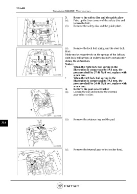
                                                          3.     Remove the safety disc and the guide plate
                                                          (a).    Prize up the four corners of the safety disc and
                                                                 loosen the bolt.
                                                          (b).    Remove the safety disc and the guide plate.


                                                          (c).    Remove the lock ball spring and the steel ball.
                                                          Hint:
                                                          Make marks respectively on the springs of the left and
                                                          right lock ball springs in order to identify conveniently
                                                          during the installation.
                                                          Notice:
                                                          •      When the right lock ball spring in the
                                                                 illustration is compressed to 19.6 mm, the
                                                                 pressure shall be 37.48 N; if not, replace with
                                                                 a new one.
                                                          •      When the left lock ball spring in the
                                                                 illustration is compressed to 19.3 mm, the
                                                                 pressure shall be 26.48 N; if not, replace with
                                                                 a new one.
                                                          4.     Remove the gear-select rocker
                                                          (a).    Loosen the nut and remove the external
                                                                 gear-select rocker.


                                                          (b).    Remove the retainer ring and the pad.
  31A


                                                          (c).    Remove the internal gear-select rocker head.


                                                                                                         Page 914
   909   910   911   912   913   914   915   916   917   918   919