
Page 21 - Feline diagnostic imaging
P. 21
14 2 Principles of Computed Tomography and Magnetic Resonance Imaging
(a) (b) x
y
z
x y
Figure 2.1 A voxel (a) is a three-dimensional volume element containing the x, y, and z planes. The voxel will contain information
about the attenuation values (CT) or signal intensity (MR). A single voxel may contain tissue of heterogeneous attenuation or signal
values; however, only the average of these values will be displayed as a pixel (b) of uniform brightness.
(Figure 2.2). The gantry houses the X‐ray tube and detector
system that rotates around the patient table. The computer
console allows for adjusting acquisition parameters and
enabling image reconstruction. Modern CT machines are
equipped with an X‐ray tube robust enough to withstand
the demands of rapid acquisition and large‐volume
datasets.
Computed tomography images are acquired with either
sequential or spiral/helical scanning [2–4]. With sequential
scanning, the tube rotates and acquires the dataset one
slice at a time (Figure 2.3a). The table on which the patient
lays is advanced incrementally and an additional dataset is
acquired. This format was the historical method of acquir-
ing CT images; however, it necessitates longer scan times
and increases the likelihood of misregistration of struc-
tures due to patient motion such as breathing. With the
advancement of CT technology, a helical acquisition tech-
nique has been made possible [1, 3]. During helical scan-
ning, the gantry rotates as the table advances, creating a
spiral volumetric dataset (Figure 2.3b). This data volume is
then reconstructed into flat slices of voxels. This allows for
much faster scan times, reducing the chances of patient
motion, allowing dynamic contrast procedures, and
increasing the potential case load. This also allows for
smaller voxel acquisition, resulting in improved image
reconstruction [1, 2]. Because this type of scanning does
place increased demands on the X‐ray tube, sequential
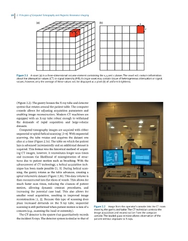
scanning is still performed when patient motion is less of a Figure 2.2 Image from the operator’s console into the CT room
concern (e.g., scanning the head or extremity). showing the gantry and table. The CT technician controls the
image acquisition and reconstruction from the computer
The CT detector is the system that quantitatively records console. The leaded glass window allows observation of the
the incident X‐rays. The detector system is similar to that of patient without exposure to X-rays.