
Page 318 - Programmable Logic Controllers, Fifth Edition - Mobile version
P. 318
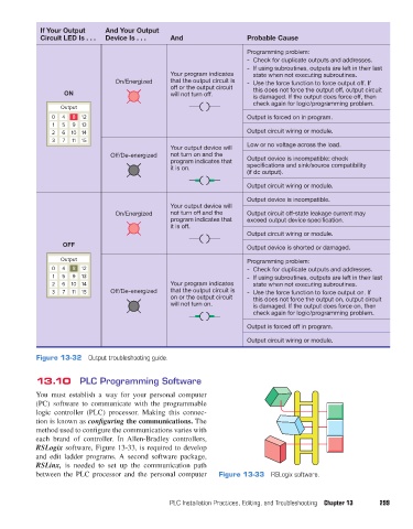
If Your Output     And Your Output
                    Circuit LED Is . . .  Device Is . . .  And                   Probable Cause
                                                                                 Programming problem:
                                                                                 -  Check for duplicate outputs and addresses.
                                                                                 -  If using subroutines, outputs are left in their last
                                                           Your program indicates   state when not executing subroutines.
                                          On/Energized     that the output circuit is   -  Use the force function to force output off. If
                                                           off or the output circuit   this does not force the output off, output circuit
                           ON                              will not turn off.      is damaged. If the output does force off, then
                                                                                   check again for logic/programming problem.
                          Output
                        0  4  8  12                                              Output is forced on in program.
                        1  5  9  13
                        2  6  10 14                                              Output circuit wiring or module.
                        3  7  11  15
                                                           Your output device will   Low or no voltage across the load.
                                         Off/De-energized   not turn on and the
                                                           program indicates that   Output device is incompatible: check
                                                           it is on.             specifications and sink/source compatibility
                                                                                 (if dc output).
                                                                                 Output circuit wiring or module.

                                                                                 Output device is incompatible.
                                                           Your output device will
                                          On/Energized     not turn off and the   Output circuit off-state leakage current may
                                                             program indicates that     exceed output device specification.
                                                           it is off.
                                                                                 Output circuit wiring or module.
                           OFF                                                   Output device is shorted or damaged.

                          Output                                                 Programming problem:
                        0  4  8  12                                              -  Check for duplicate outputs and addresses.
                        1  5  9  13                                              -  If using subroutines, outputs are left in their last
                        2  6  10 14                        Your program indicates   state when not executing subroutines.
                        3  7  11  15     Off/De-energized  that the output circuit is   -  Use the force function to force output on. If
                                                           on or the output circuit   this does not force the output on, output circuit
                                                           will not turn on.       is damaged. If the output does force on, then
                                                                                   check again for logic/programming problem.

                                                                                 Output is forced off in program.
                                                                                 Output circuit wiring or module.

                   Figure 13-32  Output troubleshooting guide.


                   13.10  PLC Programming Software

                   You  must establish  a way  for  your  personal  computer
                   (PC)  software  to communicate  with the  programmable
                   logic controller (PLC) processor. Making this connec-
                   tion is known as configuring the communications. The
                   method used to configure the communications varies with
                   each brand of controller. In  Allen-Bradley controllers,
                   RSLogix software, Figure 13-33, is required to develop
                   and edit ladder programs. A second software package,
                   RSLinx, is needed to set up the communication path
                   between the PLC processor and the personal computer   Figure 13-33  RSLogix software.


                                                          PLC Installation Practices, Editing, and Troubleshooting  Chapter 13  299


          pet73842_ch13_281-304.indd   299                                                                              03/11/15   7:23 PM