
Page 319 - Programmable Logic Controllers, Fifth Edition - Mobile version
P. 319
SLC 5/04 CPU
RUN FORCE
FLT DH+
BATT R3232
RUN REM PROG
Send
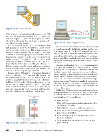
Figure 13-34 RSLinx software.
2 Send Send 2
(PC). You cannot download multiple projects to the PLC 3 Receive Receive 3
and then run them when required. The PLC will accept
only one program at a time, but the program can consist 7 Ground (common) 7
of multiple subroutine files which can be conditionally
called from the main program. Figure 13-36 Serial wiring connection.
RSLinx software, Figure 13-34, is available in mul-
tiple packages to meet the demand for a variety of cost Two important aspects of the communication link must
and functionality requirements. This software package is be considered, namely, the RS-232 standard and the com-
used as the driver between your PC and PLC processor. munications protocol. The RS-232 standard specifies a
A driver is a computer program that controls a device. function for each of the wires inside the standard com-
For example, you must have the correct printer driver in- munications cable and their associated pins. Communica-
stalled in your PC in order to be able to print a word- tions protocol is a standardized method for transmitting
processing document created on your PC. RSLinx works data and/or establishing communications between differ-
much like the printer driver for RSLogix software. The ent devices.
RSLinx program must be opened and drivers configured Minimum configuration for two-way communications
before communications can be established between a PC requires the use of only three connected wires, as shown
and a PLC that is using RSLogix software. in Figure 13-36. For ease of connection, the RS-232
RSLinx allows RSLogix to communicate through an standard specifies that computer devices have male con-
interface cable to the PLC processor. The simplest con- nectors and that peripheral equipment have female con-
nection between a PC and a PLC is a point-to-point direct nectors. Direct communication between two computers,
connection through the computer serial port, as illustrated such as a PC and a PLC, does not involve intermediate pe-
in Figure 13-35. A serial cable is used to connect to your ripheral equipment. Therefore, a serial null-modem type
PC’s COM 1 or COM 2 port and to the PLC processor’s cable must be used for the connection because both the
serial communications port. With RSLinx software you PC and the PLC processor use pin 2 for data output and
can auto-configure the serial connection and thus auto- pin 3 for data input.
matically find the proper serial port configuration. RSLinx is a Windows based communication software
package developed by Rockwell Software to interface to
all of the Rockwell and A-B industrial control and auto-
Personal computer mation hardware. To setup RSLinx:
(PC)
RSLogix • Open RSLinx.
software • Click on Communications and select configure driv-
PLC ers from the dialog box.
Processor software • Select RS-232 from the available driver types.
RSLinx
• Click on add new and select your communications
port from the dialog box.
COM port • Click on auto configure to automatically set the
baud rate and parity.
Serial cable • Minimize the RSLinx window, but leave the pro-
Figure 13-35 Direct PC-to-PLC software connection. gram running.
300 Chapter 13 PLC Installation Practices, Editing, and Troubleshooting
pet73842_ch13_281-304.indd 300 03/11/15 7:23 PM