


Page 1098 - Basic Electrical Engineering
P. 1098
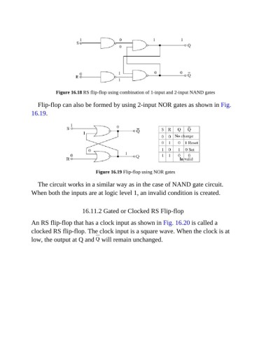
Figure 16.18 RS flip-flop using combination of 1-input and 2-input NAND gates


                  Flip-flop can also be formed by using 2-input NOR gates as shown in Fig.
               16.19.


                                             Figure 16.19 Flip-flop using NOR gates

                  The circuit works in a similar way as in the case of NAND gate circuit.

               When both the inputs are at logic level 1, an invalid condition is created.


                                       16.11.2 Gated or Clocked RS Flip-flop


               An RS flip-flop that has a clock input as shown in Fig. 16.20 is called a
               clocked RS flip-flop. The clock input is a square wave. When the clock is at
               low, the output at Q and   will remain unchanged.

