


Page 1117 - Basic Electrical Engineering
P. 1117
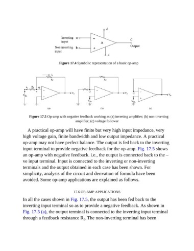
Figure 17.4 Symbolic representation of a basic op-amp


                   Figure 17.5 Op-amp with negative feedback working as (a) inverting amplifier; (b) non-inverting
                                                 amplifier; (c) voltage follower


                  A practical op-amp will have finite but very high input impedance, very
               high voltage gain, finite bandwidth and low output impedance. A practical

               op-amp may not have perfect balance. The output is fed back to the inverting
               input terminal to provide negative feedback for the op-amp. Fig. 17.5 shows
               an op-amp with negative feedback. i.e., the output is connected back to the –

               ve input terminal. Input is connected to the inverting or non-inverting
               terminals and the output obtained in each case has been shown. For

               simplicity, analysis of the circuit and derivation of formula have been
               avoided. Some op-amp applications are explained as follows.


                                               17.6 OP-AMP APPLICATIONS

               In all the cases shown in Fig. 17.5, the output has been fed back to the
               inverting input terminal so as to provide a negative feedback. As shown in

               Fig. 17.5 (a), the output terminal is connected to the inverting input terminal
               through a feedback resistance R . The non-inverting terminal has been
                                                      f

