


Page 1119 - Basic Electrical Engineering
P. 1119
The negative sign indicates that the output voltage is inverted. The closed


               loop voltage gain is        . Thus, the input voltage appears at the output terminal


               multiplied by a         and gets inverted.


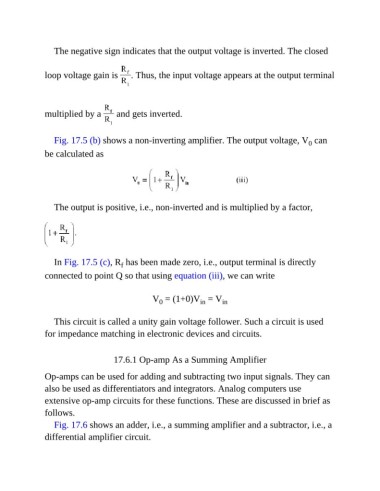
                  Fig. 17.5 (b) shows a non-inverting amplifier. The output voltage, V  can
                                                                                                    0
               be calculated as


                  The output is positive, i.e., non-inverted and is multiplied by a factor,


                  In Fig. 17.5 (c), R  has been made zero, i.e., output terminal is directly
                                        f
               connected to point Q so that using equation (iii), we can write


                                                  V  = (1+0)V  = V       in
                                                                 in
                                                    0
                  This circuit is called a unity gain voltage follower. Such a circuit is used

               for impedance matching in electronic devices and circuits.


                                      17.6.1 Op-amp As a Summing Amplifier

               Op-amps can be used for adding and subtracting two input signals. They can

               also be used as differentiators and integrators. Analog computers use
               extensive op-amp circuits for these functions. These are discussed in brief as
               follows.

                  Fig. 17.6 shows an adder, i.e., a summing amplifier and a subtractor, i.e., a
               differential amplifier circuit.

