
Page 733 - Basic Electrical Engineering
P. 733
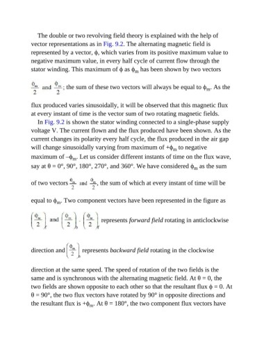
The double or two revolving field theory is explained with the help of
               vector representations as in Fig. 9.2. The alternating magnetic field is
               represented by a vector, ϕ, which varies from its positive maximum value to

               negative maximum value, in every half cycle of current flow through the
               stator winding. This maximum of ϕ as ϕ  has been shown by two vectors
                                                                m


                                the sum of these two vectors will always be equal to ϕ . As the
                                                                                                 m


               flux produced varies sinusoidally, it will be observed that this magnetic flux
               at every instant of time is the vector sum of two rotating magnetic fields.

                  In Fig. 9.2 is shown the stator winding connected to a single-phase supply
               voltage V. The current flown and the flux produced have been shown. As the

               current changes its polarity every half cycle, the flux produced in the air gap
               will change sinusoidally varying from maximum of +ϕ  to negative
                                                                                 m
               maximum of –ϕ . Let us consider different instants of time on the flux wave,
                                   m
               say at θ = 0°, 90°, 180°, 270°, and 360°. We have considered ϕ  as the sum
                                                                                           m


               of two vectors                 , the sum of which at every instant of time will be


               equal to ϕ . Two component vectors have been represented in the figure as
                           m


                                                represents forward field rotating in anticlockwise


               direction and           represents backward field rotating in the clockwise


               direction at the same speed. The speed of rotation of the two fields is the

               same and is synchronous with the alternating magnetic field. At θ = 0, the
               two fields are shown opposite to each other so that the resultant flux ϕ = 0. At

               θ = 90°, the two flux vectors have rotated by 90° in opposite directions and
               the resultant flux is +ϕ . At θ = 180°, the two component flux vectors have
                                          m