Page 195 - Fiber Optic Communications Fund
P. 195

176                                                               Fiber Optic Communications


                       11   00  10   01
                                                          1   1   0  0   1    0  0   1
                            3π
                   Phase (rad)  π  2  π              Phase (rad)  π

                                 2
                                              t                                              t
                        T s
                                                          T b
                                 (a)                                      (b)
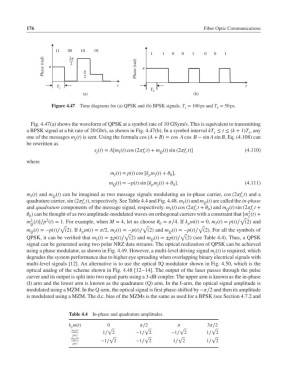
                      Figure 4.47  Time diagrams for (a) QPSK and (b) BPSK signals. T = 100 ps and T = 50 ps.
                                                                                  b
                                                                       s
              Fig. 4.47(a) shows the waveform of QPSK at a symbol rate of 10 GSym/s. This is equivalent to transmitting
            a BPSK signal at a bit rate of 20 Gb/s, as shown in Fig. 4.47(b). In a symbol interval kT ≤ t ≤ (k + 1)T ,any
                                                                                 s            s
            one of the messages m (t) is sent. Using the formula cos (A + B)= cos A cos B − sin A sin B, Eq. (4.108) can
                              j
            be rewritten as
                                     s (t)= A[m (t) cos (2f t)+ m (t) sin (2f t)]        (4.110)
                                      j       I         c    Q         c
            where

                                           m (t)= p(t) cos [k m (t)+  ],
                                             I           p  j    0
                                           m (t)=−p(t) sin [k m (t)+  ].                   (4.111)
                                            Q             p  j    0
            m (t) and m (t) can be imagined as two message signals modulating an in-phase carrier, cos (2f t) and a
              I       Q                                                                    c
            quadrature carrier, sin (2f t), respectively. See Table 4.4 and Fig. 4.48. m (t) and m (t) are called the in-phase
                                 c                                    I       Q
            and quadrature components of the message signal, respectively. m (t) cos (2f t +  ) and m (t) sin (2f t +
                                                                 I         c   0      Q        c
                                                                                              2
             ) can be thought of as two amplitude-modulated waves on orthogonal carriers with a constraint that [m (t)+
             0
                                                                                           √  I
                    2
              2
            m (t)]∕p (t)= 1. For example, when M = 4, let us choose  = ∕4. If k m(t)= 0, m (t)= p(t)∕ (2) and
              Q                                              0          p         I
                         √                             √                    √
            m (t)=−p(t)∕ (2).If k m(t)= /2, m (t)=−p(t)∕ (2) and m (t)=−p(t)∕ (2). For all the symbols of
                                                                 Q
                                             I
              Q
                                 p
                                                √                    √
            QPSK, it can be verified that m (t)=±p(t)∕ (2) and m (t)=±p(t)∕ (2) (see Table 4.4). Thus, a QPSK
                                                          Q
                                      I
            signal can be generated using two polar NRZ data streams. The optical realization of QPSK can be achieved
            using a phase modulator, as shown in Fig. 4.49. However, a multi-level driving signal m (t) is required, which
                                                                                 j
            degrades the system performance due to higher eye spreading when overlapping binary electrical signals with
            multi-level signals [12]. An alternative is to use the optical IQ modulator shown in Fig. 4.50, which is the
            optical analog of the scheme shown in Fig. 4.48 [12–14]. The output of the laser passes through the pulse
            carver and its output is split into two equal parts using a 3-dB coupler. The upper arm is known as the in-phase
            (I) arm and the lower arm is known as the quadrature (Q) arm. In the I-arm, the optical signal amplitude is
            modulated using a MZM. In the Q-arm, the optical signal is first phase-shifted by −∕2 and then its amplitude
            is modulated using a MZM. The d.c. bias of the MZMs is the same as used for a BPSK (see Section 4.7.2 and
                            Table 4.4  In-phase and quadrature amplitudes.
                            k m(t)        0           ∕2                   3∕2
                             p
                             m I (t)      √             √            √          √
                                        1∕ 2         −1∕ 2        −1∕ 2        1∕ 2
                             p(t)
                             m Q (t)       √            √           √           √
                                        −1∕ 2        −1∕ 2        1∕ 2         1∕ 2
                             p(t)
   190   191   192   193   194   195   196   197   198   199   200