
Page 191 - Fiber Optic Communications Fund
P. 191
172 Fiber Optic Communications
u (t)
in
2
1
u out (t) = [u (t) − u (t − τ)]
in
in
u (t) 2
in
Phase
Delay
shift
(t) π (t) τ (t − τ)
u in −u in −u in
2 2 2
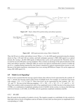
Figure 4.39 Mach–Zehner DI to perform delay-and-subtract operation.
Differential coding
DI
Polar NRZ data MZM
AMI signal
π τ
Delay T b
Laser
Figure 4.40 AMI signal generation using a Mach–Zehnder DI.
Thus, the DI acts as a delay-and-subtract circuit. When = T , the AMI signals generated using the schemes
b
shown in Figs. 4.38 and 4.40 are similar, and both techniques generate a NRZ-AMI signal in an optical
domain. By varying , the RZ-AMI signals of different duty cycles can be generated [8]. Therefore, there is
no need for an active RZ pulse-carving modulator. This is clearly an advantage of the optical realization of the
delay-and-subtract operation. Although AMIs are used in non-optical communication systems to enable the
use of a.c. coupling during transmission, this format is beneficial in optical communication systems as well.
Because of the phase transitions, intrachannel four-wave mixing (IFWM)(see Chapter 10) can be suppressed
using a RZ-AMI signal [11].
∗
4.9 Multi-Level Signaling
So far we have assumed that the message signal is binary data with two levels represented by the symbols ‘0’
and ‘1’. Instead, the message signal could consist of multiple levels. For example, we could have four levels
with voltages −3 V, −1 V,1 V, and 3 V. These four levels can be represented by four symbols, ‘00’, ‘01’,
‘10’, and ‘11’. We may do the following mapping: −3 V → ‘00’, −1 V → ‘01’, 1 V → ‘11’, and 3 V → ‘10’.
These four symbols could correspond not only to four amplitude levels (4-ASK), but also to four phase levels
(4-PSK), or a combination of amplitude and phase levels (4-QAM). In this section, we discuss the following
multi-level formats: (i) M-ASK, (ii) M-PSK, and (iii) quadrature amplitude modulation (QAM).
4.9.1 M-ASK
Here M stands for the number of symbols or levels. The simplest example we could think of is the switch of a
flash light with two levels of brightness and an off button. In total, there are three power (or amplitude) levels
corresponding to 3-ASK.