
Page 188 - Fiber Optic Communications Fund
P. 188
Optical Modulators and Modulation Schemes 169
Differential coding
Polar NRZ data
Duobinary m(t)
b'(t) encoder
b(t)
MZM
Delay T
b
A 0 out
A 0
t
Laser
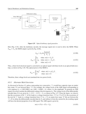
Figure 4.35 Optical duobinary signal generation.
filter (Fig. 4.34). After the duobinary encoder, the message signal m(t) is used to drive the MZM. When
V bias = V , the MZM output is given by Eq. (4.60),
[ ]
m(t)
A out = A sin , (4.100)
0
V
⎧ A when m(t)= V ∕2
0
⎪
A = −A when m(t)=−V ∕2 . (4.101)
out ⎨ 0
0 when m(t)= 0
⎪
⎩
Thus, a three-level electrical signal is converted to an optical signal with three levels in an optical field enve-
lope, as shown in Fig. 4.36. The optical power of the MZM is
{ 2
| A | when m(t)=±V ∕2
P out = | 0| . (4.102)
0 when m(t)= 0
Therefore, three voltage levels are translated into two power levels.
4.8.1 Alternate Mark Inversion
As discussed in Section 4.2, pulses representing two consecutive, ‘1’s would have opposite signs no matter
how many ‘0’s are between these ‘1’s. For example, the voltage levels of the AMI signal corresponding to
a bit sequence b ={100110001} are {A00 − AA000 − A}, where A is the amplitude. To generate an AMI
n
signal, let us first consider the differential coding of the bit sequence b . The voltage levels of the differentially
n
′
encoded data b (t) are given by {−1111 − 11111 − 1}, as shown in Fig. 4.37. From the figure, we observe
′
that the occurrence of bit ‘1’ of b(t) leads to a voltage transition from −1 V to 1 V of b (t); the occurrence of
the next bit ‘1’ leads to a voltage transition from 1 V to −1 V, no matter how many ‘0’ bits are between the
‘1’s. If we delay the differentially encoded data by T and subtract it from the current bit, the resulting signal
b
will have the desired properties of an AMI signal. The AMI signal is given by
′
′
m(t)= b (t)− b (t − T ). (4.103)
b