Page 332 - Fiber Optic Communications Fund
P. 332

Transmission System Design                                                         313


                                            P = 1.99 × 10 −5  mW.                           (7.81)
                                              1r
           The mean of bit ‘1’ is
                                                   √
                                             I = 2R P P    ,                                (7.82)
                                                      1r LO
                                              1
                                               = 2.46 × 10 −2  mA.                          (7.83)
           The noise variance of ‘1’ may be calculated as before,
                                        2
                                        = 2qB R(P + P  )+ 4k TB ∕R                        (7.84)
                                        1     e   1r   LO    B   e  L
                                                       2
                                         = 2.22 × 10 −11  A .                               (7.85)
           For bit ‘0’,

                                             I =−I 1                                        (7.86)
                                             0
                                              =−2.46 × 10 −2  mA,
                                                   =  .                                 (7.87)
                                                        1
                                                   0
           Therefore, the Q-factor is
                                                    I 1
                                               Q =    = 5.23.                               (7.88)
                                                   
                                                     1
           The approximate Q-factor for PSK is given by Eq. (7.62),
                                                     √
                                                        2P 1r
                                               Q PSK  =                                     (7.89)
                                                        hfB
                                                           e
                                                   = 5.38.                                  (7.90)


           7.3  Dispersion-Induced Limitations

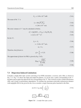
           Consider a simple fiber-optic system consisting of an OOK transmitter, a receiver, and a fiber, as shown in
           Fig. 7.11. Fig. 7.12 shows the input and output bit patterns. As can be seen, a pulse corresponding to bit ‘1’
           broadens and occupies the adjacent bit slot corresponding to bit ‘0’. This is known as inter-symbol interference
           (ISI), and it leads to performance degradation. To estimate the maximum achievable transmission distance
           with negligible ISI for the given bit rate, let us consider a single Gaussian pulse launched to the fiber,
                                                        (     )
                                                            t 2
                                           u(t, 0)= A exp −     .                           (7.91)
                                                   in        2
                                                           2T
                                                             0


                                      Figure 7.11  A simple fiber-optic system.
   327   328   329   330   331   332   333   334   335   336   337