
Page 328 - Fiber Optic Communications Fund
P. 328
Transmission System Design 309
−9
less than 18 for an OOK system, the BER exceeds 10 . Since P = P exp(−L), the maximum transmission
r in
distance at which the mean number of photons becomes equal to 18 can easily be calculated. For example,
when the peak fiber launch power P = 2 dBm and bit rate = 10 Gb/s, the peak received power is
in
P (dBm)= P (dBm)− loss(dB), (7.56)
r in
N hf
1r
P = , (7.57)
r
T
b
P (dBm)= 10 log (2N hfB) (7.58)
rec
r
10
=−43.3dBm,
where N rec = 18 and f = 193.54 THz is used. From Eq. (7.56), we find
loss(dB)= P (dBm)− P (dBm) (7.59)
in
r
= 2dBm −(−43.3) dBm
= 45.3dB.
With fiber loss coefficient = 0.2 dB/km, the maximum transmission distance to reach the BER of 10 −9 is
about 225 km. This should be compared with the results shown in Fig. 7.4 for the case of a direct detection
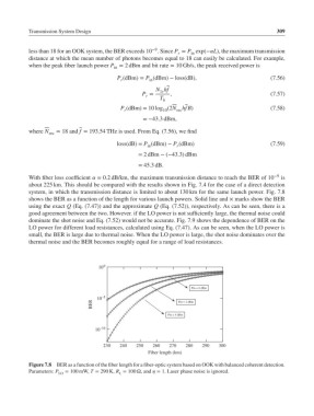
system, in which the transmission distance is limited to about 130 km for the same launch power. Fig. 7.8
shows the BER as a function of the length for various launch powers. Solid line and × marks show the BER
using the exact Q (Eq. (7.47)) and the approximate Q (Eq. (7.52)), respectively. As can be seen, there is a
good agreement between the two. However. if the LO power is not sufficiently large, the thermal noise could
dominate the shot noise and Eq. (7.52) would not be accurate. Fig. 7.9 shows the dependence of BER on the
LO power for different load resistances, calculated using Eq. (7.47). As can be seen, when the LO power is
small, the BER is large due to thermal noise. When the LO power is large, the shot noise dominates over the
thermal noise and the BER becomes roughly equal for a range of load resistances.
10 0
Pin = 0 dBm
10 –5
BER Pin = 2 dBm
Pin = 4 dBm
10 –10
230 240 250 260 270 280 290 300
Fiber length (km)
Figure 7.8 BER as a function of the fiber length for a fiber-optic system based on OOK with balanced coherent detection.
Parameters: P = 100 mW, T = 290 K, R = 100 Ω,and = 1. Laser phase noise is ignored.
LO L