
Page 325 - Fiber Optic Communications Fund
P. 325
306 Fiber Optic Communications
b = 4k TB ∕R L
e
B
4 × 1.38 × 10 −23 × 298 × 7 × 10 9 2
= A
50
2
= 2.3 × 10 −12 A . (7.24)
Rearranging Eq. (7.21), we have
RP √
√ 1r
aP + b = − b. (7.25)
1r
Q
Squaring Eq. (7.25) and simplifying, we obtain
√
( ) 2
RP 1r 2RP 1r b
aP = − . (7.26)
1r
Q Q
or √
2 b aQ 2
P = + . (7.27)
1r 2
RQ R
When Q = 6,
√
2 × 2.3 × 10 −12 −9
P = + 2.24 × 10 × 36
1r
6
= 1.829 mW. (7.28)
From Eq. (7.22),
P = P exp (L)
in 1r
= 1.829 × 10 −2 × exp (0.046 × 130)
= 7.23 mW. (7.29)
The lower limit on the transmitter peak power is 7.23 mW. If P < 7.23 mW, Q < 6.
in
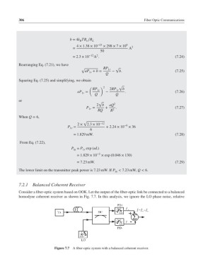
7.2.1 Balanced Coherent Receiver
Consider a fiber-optic system based on OOK. Let the output of the fiber-optic link be connected to a balanced
homodyne coherent receiver as shown in Fig. 7.7. In this analysis, we ignore the LO phase noise, relative
Figure 7.7 A fiber-optic system with a balanced coherent receiver.