Page 321 - Fiber Optic Communications Fund
P. 321

302                                                               Fiber Optic Communications


                    Figure 7.1 A simple fiber-optic system consisting of a transmitter, a receiver, and an optical fiber.


            The total variance is
                                     2
                                     =  2  +  2  = 2qI B + 4K TB ∕R .                    (7.6)
                                     1    1,shot  1,thermal  1 e   B  e  L
            For bit ‘0’, the mean photocurrent I is zero and, therefore, the shot noise variance is negligible. The total
                                         0
            noise variance is
                                                 2
                                                 = 4K TB ∕R .                                (7.7)
                                                 0     B  e  L
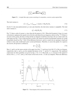
            Fig. 7.2 shows a plot of current vs. time when the bit pattern is 1011. When the bit pattern is long, it is more
            convenient to superpose the signals in two bit slots and obtain the eye diagram as shown in Fig. 7.3. If there is
            no noise in the system, the lines overlap and the eye diagram would have four lines; the eye is then said to be
            wide open (see Fig. 7.3(a)). In the presence of noise, the current in each bit slot fluctuates and the eye would
            be partially closed (see Fig. 7.3(b)). If the difference between I and I is small, the eye opening is small and
                                                              1     0
            if there is noise, this would lead to poor system performance. Therefore, to assess the quality of a signal at
            the receiver, the Q-factor is defined as
                                                       I − I 0
                                                       1
                                                  Q =       .                                  (7.8)
                                                       + 
                                                       1   0
            Here, I and I are the mean currents at the upper level (bit ‘1’) and lower level (bit ‘0’) of the eye diagram,
                  1    0
            respectively, and  and  are the standard deviations of bit ‘1’ and bit ‘0’, respectively. The analytical
                            1     0
            expressions for these quantities are given by Eqs. (7.4)–(7.7). Physically,  is a measure of the spread of
                                                                          j
            levels of bit ‘j’, j = 0, 1, and I is the mean of the levels of bit ‘j’ in the eye diagram. When the difference
                                     j
                                  1.6
                                           1       0         1     1
                                  1.4

                                  1.2
                                   1                                          I 1
                                Current, I   0.8

                                  0.6
                                  0.4
                                  0.2
                                                                             I
                                                                              0
                                   0
                                  0.2
                                        0       1      2       3       4       5
                                                       Time, t/T b
                                   Figure 7.2 Time diagram of the current at the receiver.
   316   317   318   319   320   321   322   323   324   325   326