
Page 323 - Fiber Optic Communications Fund
P. 323
304 Fiber Optic Communications
10 0
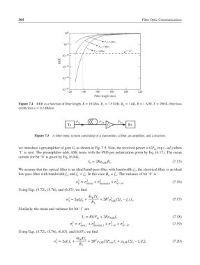
P in = 0 dBm
10 –5
P in = 2 dBm
9
P in = 4 dBm 10
10 –10
BER
10 –15
10 –20
10 –25
120 140 160 180 200 220
Fiber length (km)
Figure 7.4 BER as a function of fiber length. B = 10 Gb/s, B = 7.5 GHz, R = 1kΩ, R = 1 A/W, T = 290 K, fiber loss
e
L
coefficient = 0.2 dB/km.
Figure 7.5 A fiber-optic system consisting of a transmitter, a fiber, an amplifier, and a receiver.
we introduce a preamplifier of gain G, as shown in Fig. 7.5. Now, the received power is GP exp (−L) when
in
‘1’ is sent. The preamplifier adds ASE noise with the PSD per polarization given by Eq. (6.17). The mean
current for bit ‘0’ is given by Eq. (6.84),
I = 2R ASE o (7.15)
B .
0
We assume that the optical filter is an ideal band-pass filter with bandwidth f , the electrical filter is an ideal
o
low-pass filter with bandwidth f , and f < f . In this case B = f . The variance of bit ‘0’ is
e
o
o
e
o
2 2 2 2
= + + . (7.16)
0 shot,0 thermal,0 sp−sp
Using Eqs. (5.72), (5.76), and (6.87), we find
4k Tf e 2 2
B
2
= 2qI f + + 2R (2f − f ) f . (7.17)
0 0 e R ASE o e e
L
Similarly, the mean and variance for bit ‘1’ are
I = RGP + 2R f , (7.18)
1 in ASE o
2
= 2 + 2 + 2 + 2 . (7.19)
1 shot,1 thermal,1 s−sp sp−sp
Using Eqs. (5.72), (5.76), (6.83), and (6.87), we find
4k Tf
2 B e 2
= 2qI f + + 2R [2P f + (2f − f )f ]. (7.20)
1 1 e R ASE out e ASE o e e
L