
Page 330 - Fiber Optic Communications Fund
P. 330
Transmission System Design 311
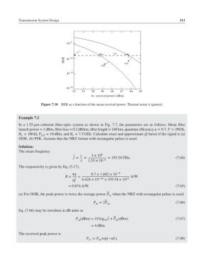
10 –5
–9
10
3 dB
BER 10 –10
OOK
PSK
10 –15
10 –20
52 51 50 49 48 47 46 45
Av. received power (dBm)
Figure 7.10 BER as a function of the mean received power. Thermal noise is ignored.
Example 7.2
In a 1.55-μm coherent fiber-optic system as shown in Fig. 7.7, the parameters are as follows. Mean fiber
launch power = 1 dBm, fiber loss = 0.2 dB/km, fiber length = 240 km, quantum efficiency = 0.7, T = 290 K,
R = 100 Ω, P LO = 10 dBm, and B = 7.5 GHz. Calculate exact and approximate Q-factor if the signal is (a)
e
L
OOK, (b) PSK. Assume that the NRZ format with rectangular pulses is used.
Solution:
The mean frequency
c 3 × 10 8
f = = = 193.54 THz. (7.64)
1.55 × 10 −6
The responsivity is given by Eq. (5.17),
q 0.7 × 1.602 × 10 −9
R = = −34 12 A/W.
hf 6.626 × 10 × 193.54 × 10
= 0.874 A/W. (7.65)
(a) For OOK, the peak power is twice the average power P when the NRZ with rectangular pulses is used:
in
P = 2P . (7.66)
in
in
Eq. (7.66) may be rewritten in dB units as
P (dBm)= 10 log 2 + P (dBm) (7.67)
10
in
in
= 4dBm.
The received peak power is
P = P exp(−L), (7.68)
1r in