Page 336 - Fiber Optic Communications Fund
P. 336

Transmission System Design                                                         317


           In this section, we assume ideal in-line amplifiers. If EDFAs are used as in-line amplifiers, the saturation
           power of each successive amplifier has to be increased slightly to compensate for the gain saturation caused
           by the build-up of the ASE [5]. The optical signal-to-noise ratio is defined as (Eq. (6.107))
                                                  mean signal power
                                 OSNR =                                   ,                (7.109)
                                         mean noise power in a bandwidth of B opt

           where B opt  is the reference bandwidth, typically chosen to be 12.5 GHz. The noise power in both polarizations
           is twice that given by Eq. (7.107). Using Eqs. (7.103) and (7.107), we find the OSNR at the receiver to be

                                                        P in
                                         OSNR =                  .                         (7.110)
                                                 2Nn hf(G − 1)B opt
                                                     sp
           Sometimes, it is convenient to express OSNR in dB units. Assuming G ≫ 1 and noise figure F ≅ 2n , and
                                                                                           sp
                                                                                      n
           dividing the numerator and denominator of Eq. (7.110) by 1 mW, it can be written in dB units as
                                                                          (       )
                                                                            hfB opt
                        OSNR(dB)= P [dBm]− N[dB]− G[dB]− F [dB]− 10 log  10
                                    in
                                                             n
                                                                            1mW
                                 = P [dBm]− N[dB]− G[dB]− F [dB]+ 58,                      (7.111)
                                    in                       n
           wherewehaveused f = 194 THz.


           7.4.1  Equivalent Noise Figure
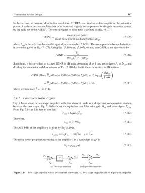
           Fig. 7.14(a) shows a two-stage amplifier with loss element, such as a dispersion compensation module
           between the two stages. Fig. 7.14(b) shows the equivalent amplifier with gain G eq  and noise figure F n,eq .
           From Fig. 7.14(a), it is easy to see that
                                              P out  = G HG P .                            (7.112)
                                                     1
                                                         2 in
           Therefore,
                                                G eq  = G HG .                             (7.113)
                                                          2
                                                       1
           The ASE PSD of the amplifier j is given by Eq. (6.102),
                                          =(G F   − 1) hf∕2,  j = 1, 2.                  (7.114)
                                        ASE,j   j n, j
           The noise power per polarization due to the amplifier 1 in a bandwidth of Δf is

                                                N =    Δf.                               (7.115)
                                                 1   ASE,1


                                      (a) Two-stage amplifier  (b) Equivalent amplifier

           Figure 7.14 Two-stage amplifier with a loss element in between. (a) Two-stage amplifier and (b) Equivalent amplifier.
   331   332   333   334   335   336   337   338   339   340   341