
Page 45 - Fiber Optic Communications Fund
P. 45
26 Fiber Optic Communications
Example 1.8
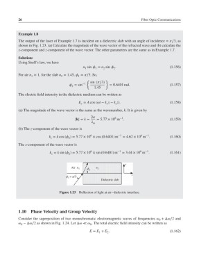
The output of the laser of Example 1.7 is incident on a dielectric slab with an angle of incidence = ∕3, as
shown in Fig. 1.23. (a) Calculate the magnitude of the wave vector of the refracted wave and (b) calculate the
x-component and z-component of the wave vector. The other parameters are the same as in Example 1.7.
Solution:
Using Snell’s law, we have
n sin = n sin . (1.156)
1
1
2
2
For air n ≈ 1, for the slab n = 1.45, = ∕3. So,
1 2 1
{ }
sin (∕3)
−1
= sin = 0.6401 rad. (1.157)
2
1.45
The electric field intensity in the dielectric medium can be written as
E = A cos (t − k x − k z). (1.158)
y x z
(a) The magnitude of the wave vector is the same as the wavenumber, k. It is given by
2 6 −1
|k| = k = = 5.77 × 10 m . (1.159)
m
(b) The z-component of the wave vector is
6
6
−1
k = k cos ( )= 5.77 × 10 × cos (0.6401) m −1 = 4.62 × 10 m . (1.160)
z
2
The x-component of the wave vector is
6
−1
6
k = k sin ( )= 5.77 × 10 × sin (0.6401) m −1 = 3.44 × 10 m . (1.161)
x
2
x
Air n 1 ϕ 2 n 2
z
ϕ 1 = π/3
Dielectric slab
Figure 1.23 Reflection of light at air–dielectric interface.
1.10 Phase Velocity and Group Velocity
Consider the superposition of two monochromatic electromagnetic waves of frequencies +Δ∕2 and
0
−Δ∕2 as shown in Fig. 1.24. Let Δ≪ . The total electric field intensity can be written as
0 0
E = E + E . (1.162)
1 2