
Page 106 - Computer Graphics Handout
P. 106
We will study this transformation in Chapter 4. After this transformation, vertices are still represented in homogeneous coordinates.
The division by the w component, called perspective division, yields three-dimensional representations in normalized device
coordinates. The final transformation takes a position in normalized device coordinates and, taking into account the viewport,
creates a three-dimensional representation in window coordinates. Window coordinates are measured in units of pixels on the
display but retain depth information. If we remove the depth coordinate, we are working with two-dimensional screen coordinates.
The application programmer usually works with two frames: the eye frame and the object frame. By concatenating them together
to form the model-view matrix, we have a transformation that positions the object frame relative to the eye frame. Thus, the model-
view matrix converts the homogeneous-coordinate representations of points and vectors to their representations in the application
space to their representations in the eye frame.
Although an application does not require us to use the model-view matrix, the model-view matrix is so important to most
applications that we will almost always include it in our examples. One of the issues we will discuss in some detail is where we
specify our transformations and where they are applied. For example, we could specify a transformation in the application and apply
it to the data there. We could also define the parameters of a transformation in the application and send these parameters to the
shaders and let the GPU carry out the transformations. We examine these approaches in the following sections.
Let’s assume that we allocate a model-view matrix in our applications and initialize it to an identity matrix. Now the object frame
and eye frame are identical. Thus, if we do not change the model-view matrix, we are working in eye coordinates.
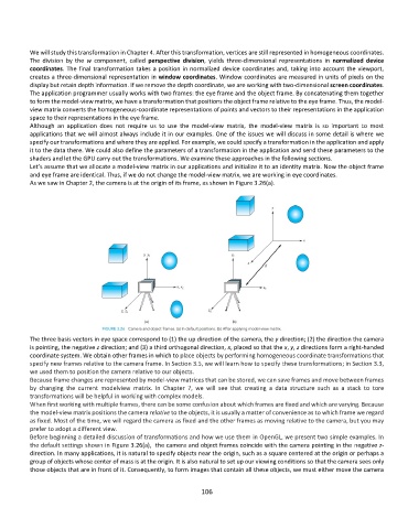
As we saw in Chapter 2, the camera is at the origin of its frame, as shown in Figure 3.26(a).
The three basis vectors in eye space correspond to (1) the up direction of the camera, the y direction; (2) the direction the camera
is pointing, the negative z direction; and (3) a third orthogonal direction, x, placed so that the x, y, z directions form a right-handed
coordinate system. We obtain other frames in which to place objects by performing homogeneous coordinate transformations that
specify new frames relative to the camera frame. In Section 3.5, we will learn how to specify these transformations; in Section 3.3,
we used them to position the camera relative to our objects.
Because frame changes are represented by model-view matrices that can be stored, we can save frames and move between frames
by changing the current modelview matrix. In Chapter 7, we will see that creating a data structure such as a stack to tore
transformations will be helpful in working with complex models.
When first working with multiple frames, there can be some confusion about which frames are fixed and which are varying. Because
the model-view matrix positions the camera relative to the objects, it is usually a matter of convenience as to which frame we regard
as fixed. Most of the time, we will regard the camera as fixed and the other frames as moving relative to the camera, but you may
prefer to adopt a different view.
Before beginning a detailed discussion of transformations and how we use them in OpenGL, we present two simple examples. In
the default settings shown in Figure 3.26(a), the camera and object frames coincide with the camera pointing in the negative z-
direction. In many applications, it is natural to specify objects near the origin, such as a square centered at the origin or perhaps a
group of objects whose center of mass is at the origin. It is also natural to set up our viewing conditions so that the camera sees only
those objects that are in front of it. Consequently, to form images that contain all these objects, we must either move the camera
106