
Page 109 - Computer Graphics Handout
P. 109
be represented, like two-dimensional objects, through a set of vertices, we will see that data
structures will help us to incorporate the relationships among the vertices, edges, and faces of
geometric objects. Such data structures are supported in OpenGL through a facility called vertex
arrays, which we introduce at the end of this section.
After we have modeled the cube, we can animate it by using affine transformations. We introduce
these transformations in Section 3.7 and then use them to alter a model-view matrix. In Chapter
4, we use these transformations again as part of the viewing process. Our pipeline model will
serve us well. Vertices will flow through a number of transformations in the pipeline, all of which
will use our homogeneous-coordinate representation. At the end of the pipeline awaits the
rasterizer. At this point, we can assume it will do its job automatically, provided we perform the
preliminary steps correctly.
3.6.1 Modeling the Faces
The cube is as simple a three-dimensional object as we might expect to model and display. There are a number of ways, however,
to model it. A CSG system would regard it as a single primitive. At the other extreme, the hardware processes the cube as an object
defined by eight vertices. Our decision to use surface-based models implies that we regard a cube either as the intersection of six
planes or as the six polygons, called facets, that define its faces. A carefully designed data structure should support both the high-
level application view of the cube and the low-level view needed for the implementation. We start by assuming that the vertices of
the cube are available through an array of vertices. We will work with homogeneous coordinates, so
point4 vertices[8] = {
point4(-1.0,-1.0,-1.0,1.0),point4(1.0,-1.0,-1.0,1.0),
point4(1.0,1.0,-1.0,1.0), point4(-1.0,1.0,-1.0,1.0),
point4(-1.0,-1.0,1.0,1.0), point4(1.0,-1.0,1.0,1.0)
point4(1.0,1.0,1.0,1.0), point4(-1.0,1.0,1.0,1.0)};
We can then use the list of points to specify the faces of the cube. For example, one face is given by the sequence of vertices (0, 3,
2, 1). We can specify the other five faces similarly.
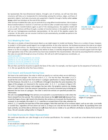
3.6.2 Inward- and Outward-Pointing Faces
We have to be careful about the order in which we specify our vertices when we are defining a
three-dimensional polygon. We used the order 0, 3, 2, 1 for the first face. The order 1, 0, 3, 2
would be the same, because the final vertex in a polygon specification is always linked back to
the first.However, the order 0, 1, 2, 3 is different. Although it describes the same boundary, the
edges of the polygon are traversed in the reverse order—0, 3, 2, 1—as shown in Figure 3.29.
The order is important because each polygon has two sides. Our graphics systems can display
either or both of them. From the camera’s perspective, we need a consistent way to distinguish
between the two faces of a polygon. The order in which the vertices are specified provides this
information.
We call a face outward facing if the vertices are traversed in a counterclockwise order when the
face is viewed from the outside. This method is also known as the right-hand rule because if you
orient the fingers of your right hand in the direction the vertices are traversed, the thumb points
outward. In our example, the order 0, 3, 2, 1 specifies an outward face of the cube, whereas the
order 0, 1, 2, 3 specifies the back face of the same polygon. Note that each face of an enclosed object, such as our cube, is an inside
or outside face, regardless of from where we view it, as long as we view the face from outside the object. By specifying front and
back carefully, we will be able to eliminate (or cull) faces that are not visible or to use different attributes to display front and back
faces. We will consider culling further in Chapter 6.
3.6.3 Data Structures for Object Representation
We could now describe our cube through a set of vertex specifications. For example, we could use a two-dimensional array of
positions
point3 faces[6][4];
or we could use a single array of 24 vertices
point3 cube_vertices[24];
109