
Page 107 - Computer Graphics Handout
P. 107
away from the objects or move the objects away from the camera. Equivalently, we move the camera frame relative to the object
frame. If we regard the camera frame as fixed and the model-view matrix as positioning the object frame relative to the camera
frame, then the model-view matrix,
moves a point (x, y, z) in the object frame to the point (x, y, z − d) in the camera frame. Thus, by making d a suitably large positive
number, we “move” the objects in front of the camera by moving the world frame relative to the camera frame, as shown in Figure
3.26(b). Note that, as far as the user—who is working in world coordinates—is concerned, she is positioning objects as before. The
model-view matrix takes care of the relative positioning of the object and eye frames. This strategy is almost always better than
attempting to alter the positions of the objects by changing their vertex positions to place them in front of the camera.
Let’s look at another example. When we define our objects using vertices, we are working in the application frame (or world frame).
The vertex positions specified there are the representation of points in that frame. Thus, we do not use the world frame directly but
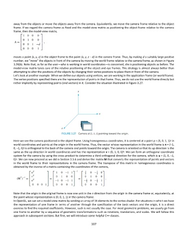
rather implicitly by representing points (and vectors) in it. Consider the situation illustrated in Figure 3.27.
Here we see the camera positioned in the object frame. Using homogeneous coordinates, it is centered at a point p = (1, 0, 1, 1)T in
world coordinates and points at the origin in the world frame. Thus, the vector whose representation in the world frame is n = (−1,
0, −1, 0)T is orthogonal to the back of the camera and points toward the origin. The camera is oriented so that its up direction is the
same as the up direction in world coordinates and has the representation v = (0, 1, 0, 0)T. We can form an orthogonal coordinate
system for the camera by using the cross product to determine a third orthogonal direction for the camera, which is u = (1, 0, −1,
0)T. We can now proceed as we did in Section 3.3.6 and derive the matrix M that converts the representation of points and vectors
in the world frame to their representations in the camera frame. The transpose of this matrix in homogeneous coordinates is
obtained by the inverse of a matrix containing the coordinates of the camera,
Note that the origin in the original frame is now one unit in the n direction from the origin in the camera frame or, equivalently, at
the point whose representation is (0, 0, 1, 1) in the camera frame.
In OpenGL, we can set a model-view matrix by sending an array of 16 elements to the vertex shader. For situations in which we have
the representation of one frame in terms of another through the specification of the basis vectors and the origin, it is a direct
exercise to find the required coefficients. However, such is not usually the case. For most geometric problems, we usually go from
one frame to another by a sequence of geometric transformations such as rotations, translations, and scales. We will follow this
approach in subsequent sections. But first, we will introduce some helpful C++ classes.
107