
Page 110 - Computer Graphics Handout
P. 110
where cube_vertices[i] contains the x, y, z coordinates of the ith vertex in the list. Both of these methods work, but they both fail to
capture the essence of the cube’s topology, as opposed to the cube’s geometry. If we think of the cube as a polyhedron, we have
an object—the cube—that is composed of six faces. The faces are each quadrilaterals that meet at vertices; each vertex is shared
by three faces. In addition, pairs of vertices define edges of the quadrilaterals; each edge is shared by two faces. These statements
describe the topology of a six-sided polyhedron. All are true, regardless of the location of the vertices—that is, regardless of the
19
geometry of the object .
Throughout the rest of this book, we will see that there are numerous advantages to building for our objects data structures that
separate the topology from the geometry. In this example, we use a structure, the vertex list, that is both simple and useful and can
be expanded later.
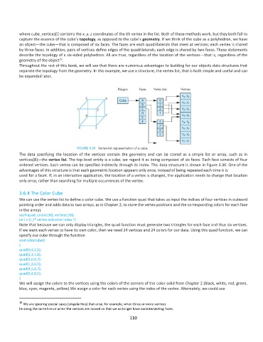
The data specifying the location of the vertices contain the geometry and can be stored as a simple list or array, such as in
vertices[8]—the vertex list. The top-level entity is a cube; we regard it as being composed of six faces. Each face consists of four
ordered vertices. Each vertex can be specified indirectly through its index. This data structure is shown in Figure 3.30. One of the
advantages of this structure is that each geometric location appears only once, instead of being repeated each time it is
used for a facet. If, in an interactive application, the location of a vertex is changed, the application needs to change that location
only once, rather than searching for multiple occurrences of the vertex.
3.6.4 The Color Cube
We can use the vertex list to define a color cube. We use a function quad that takes as input the indices of four vertices in outward
pointing order and adds data to two arrays, as in Chapter 2, to store the vertex positions and the corresponding colors for each face
in the arrays
vec4 quad_colors[36], vertices[36];
int i = 0; /* vertex and color index */
Note that because we can only display triangles, the quad function must generate two triangles for each face and thus six vertices.
If we want each vertex to have its own color, then we need 24 vertices and 24 colors for our data. Using this quad function, we can
specify our cube through the function
void colorcube()
{
quad(0,3,2,1);
quad(2,3,7,6);
quad(3,0,4,7);
quad(1,2,6,5);
quad(4,5,6,7);
quad(5,4,0,1);
}
We will assign the colors to the vertices using the colors of the corners of the color solid from Chapter 2 (black, white, red, green,
blue, cyan, magenta, yellow).We assign a color for each vertex using the index of the vertex. Alternately, we could use
19
We are ignoring special cases (singularities) that arise, for example, when three or more vertices
lie along the same line or when the vertices are moved so that we no longer have nonintersecting faces.
110