
Page 170 - Computer Graphics Handout
P. 170
at the origin in the camera frame. In principle, we should be able to specify each of the six sides of the frustum to have almost any
orientation. If we did so, however, we would make it difficult to specify a view in the application and complicate the implementation.
In practice, we rarely need this flexibility, and usually we can get by with only two perspective viewing functions. Other APIs differ
in their function calls but incorporate similar restrictions.
4.6.1 Perspective Functions
We will develop two functions for specifying perspective views and one for specifying parallel views. Alternatively, we can form the
projection matrix directly, either by loading it or by applying rotations, translations, and scalings to an initial identity matrix. We can
specify a perspective camera view by the function
mat4 Frustum(Glfloat left, Glfloat right, Glfloat bottom, Glfloat top,
Glfloat near, Glfloat far);
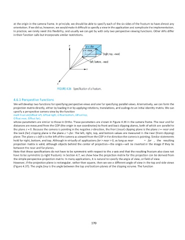
whose parameters are similar to those in Ortho. These parameters are shown in Figure 4.36 in the camera frame. The near and far
distances are measured from the COP (the origin in eye coordinates) to front and back clipping planes, both of which are parallel to
the plane z = 0. Because the camera is pointing in the negative z-direction, the front (near) clipping plane is the plane z =−near and
the back (far) clipping plane is the plane z =−far. The left, right, top, and bottom values are measured in the near (front clipping)
plane. The plane x = left is to the left of the camera as viewed from the COP in the direction the camera is pointing. Similar statements
hold for right, bottom, and top. Although in virtually all applications far > near > 0, as long as near = far , the resulting
projection matrix is valid, although objects behind the center of projection—the origin—will be inverted in the image if they lie
between the near and far planes.
Note that these specifications do not have to be symmetric with respect to the z-axis and that the resulting frustum also does not
have to be symmetric (a right frustum). In Section 4.7, we show how the projection matrix for this projection can be derived from
the simple perspective-projection matrix. In many applications, it is natural to specify the angle of view, or field of view.
However, if the projection plane is rectangular, rather than square, then we see a different angle of view in the top and side views
(Figure 4.37). The angle fovy is the angle between the top and bottom planes of the clipping volume. The function
170