
Page 166 - Computer Graphics Handout
P. 166
increase bottom and top in the y-direction. Although this distortion of the cube’s image may be annoying, it is a consequence of
using an x – y rectangle in Ortho that is not square. This rectangle is mapped to the full viewport, which has been unchanged. We
can alter the program so that we increase or decrease all of left, right, bottom, and top simultaneously or we can alter the viewport
as part of any change to Ortho (see Exercise 4.28).
4.5 PERSPECTIVE PROJECTIONS
We now turn to perspective projections, which are what we get with a camera whose lens has a finite focal length or, in terms of
our synthetic camera model, the center of projection is finite. As with parallel projections, we will separate perspective viewing into
two parts: the positioning of the camera and the projection. Positioning will be done the same way, and we can use the LookAt
function. The projection part is equivalent to selecting a lens for the camera. As we saw in Chapter 1, it is the combination of the
lens and the size of the film (or of the back of the camera) that determines how much of the world in front of a camera appears in
the image. In computer graphics, we make an equivalent choice when we select the type of projection and the viewing parameters.
With a physical camera, a wide-angle lens gives the most dramatic perspectives, with objects near the camera appearing large
compared to objects far from the lens. A telephoto lens gives an image that appears flat and is close to a parallel view.
First, we consider the mathematics for a simple projection. We can extend our use of homogeneous coordinates to the projection
process, which allows us to characterize a particular projection with a 4 × 4 matrix.
4.5.1 Simple Perspective Projections
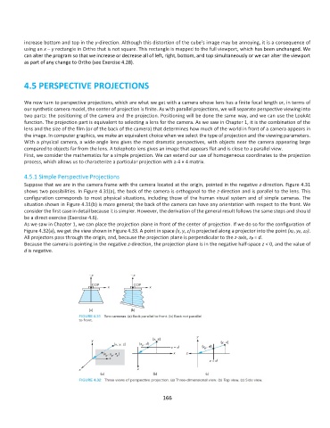
Suppose that we are in the camera frame with the camera located at the origin, pointed in the negative z-direction. Figure 4.31
shows two possibilities. In Figure 4.31(a), the back of the camera is orthogonal to the z-direction and is parallel to the lens. This
configuration corresponds to most physical situations, including those of the human visual system and of simple cameras. The
situation shown in Figure 4.31(b) is more general; the back of the camera can have any orientation with respect to the front. We
consider the first case in detail because it is simpler. However, the derivation of the general result follows the same steps and should
be a direct exercise (Exercise 4.6).
As we saw in Chapter 1, we can place the projection plane in front of the center of projection. If we do so for the configuration of
Figure 4.32(a), we get the view shown in Figure 4.33. A point in space (x, y, z) is projected along a projector into the point (xp, yp, zp).
All projectors pass through the origin, and, because the projection plane is perpendicular to the z-axis, zp = d.
Because the camera is pointing in the negative z-direction, the projection plane is in the negative half-space z < 0, and the value of
d is negative.
166