
Page 164 - Computer Graphics Handout
P. 164
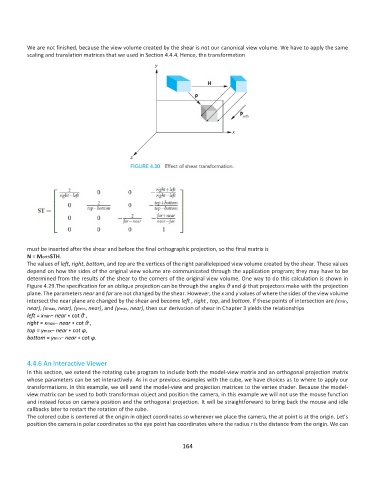
We are not finished, because the view volume created by the shear is not our canonical view volume. We have to apply the same
          scaling and translation matrices that we used in Section 4.4.4. Hence, the transformation


          must be inserted after the shear and before the final orthographic projection, so the final matrix is
          N = MorthSTH.
          The values of left, right, bottom, and top are the vertices of the right parallelepiped view volume created by the shear. These values
          depend on how the sides of the original view volume are communicated through the application program; they may have to be
          determined from the results of the shear to the corners of the original view volume. One way to do this calculation is shown in
          Figure 4.29.The specification for an oblique projection can be through the angles θ and ψ that projectors make with the projection
          plane. The parameters near and far are not changed by the shear. However, the x and y values of where the sides of the view volume
          intersect the near plane are changed by the shear and become left , right , top, and bottom. If these points of intersection are (xmin,
          near), (xmax, near), (ymin, near), and (ymax, near), then our derivation of shear in Chapter 3 yields the relationships
          left = xmin− near ∗ cot θ ,
          right = xmax− near ∗ cot θ ,
          top = ymax− near ∗ cot φ,
          bottom = ymin− near ∗ cot φ.


          4.4.6 An Interactive Viewer
          In this section, we extend the rotating cube program to include both the model-view matrix and an orthogonal projection matrix
          whose parameters can be set interactively. As in our previous examples with the cube, we have choices as to where to apply our
          transformations. In this example, we will send the model-view and projection matrices to the vertex shader. Because the model-
          view matrix can be used to both transforman object and position the camera, in this example we will not use the mouse function
          and instead focus on camera position and the orthogonal projection. It will be straightforward to bring back the mouse and idle
          callbacks later to restart the rotation of the cube.
          The colored cube is centered at the origin in object coordinates so wherever we place the camera, the at point is at the origin. Let’s
          position the camera in polar coordinates so the eye point has coordinates where the radius r is the distance from the origin. We can


                                                             164