
Page 160 - Computer Graphics Handout
P. 160
In computer graphics systems, we adopt a slightly different approach. First, we work in four dimensions using homogeneous
coordinates. Second, we retain depth information—distance along a projector—as long as possible so that we can do hidden-surface
removal later in the pipeline. Third, we use projection normalization, to convert all projections into orthogonal projections by first
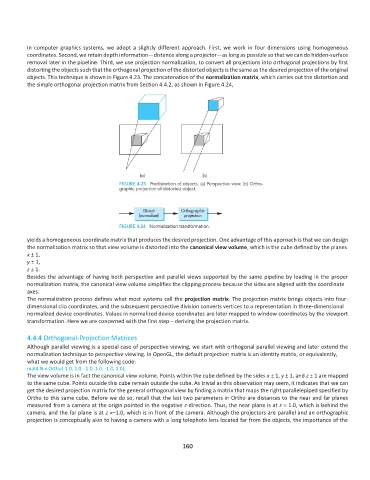
distorting the objects such that the orthogonal projection of the distorted objects is the same as the desired projection of the original
objects. This technique is shown in Figure 4.23. The concatenation of the normalization matrix, which carries out the distortion and
the simple orthogonal projection matrix from Section 4.4.2, as shown in Figure 4.24,
yields a homogeneous coordinate matrix that produces the desired projection. One advantage of this approach is that we can design
the normalization matrix so that view volume is distorted into the canonical view volume, which is the cube defined by the planes
x ± 1,
y ± 1,
z ± 1.
Besides the advantage of having both perspective and parallel views supported by the same pipeline by loading in the proper
normalization matrix, the canonical view volume simplifies the clipping process because the sides are aligned with the coordinate
axes.
The normalization process defines what most systems call the projection matrix. The projection matrix brings objects into four-
dimensional clip coordinates, and the subsequent perspective division converts vertices to a representation in three-dimensional
normalized device coordinates. Values in normalized device coordinates are later mapped to window coordinates by the viewport
transformation. Here we are concerned with the first step—deriving the projection matrix.
4.4.4 Orthogonal-Projection Matrices
Although parallel viewing is a special case of perspective viewing, we start with orthogonal parallel viewing and later extend the
normalization technique to perspective viewing. In OpenGL, the default projection matrix is an identity matrix, or equivalently,
what we would get from the following code:
mat4 N = Ortho(-1.0, 1.0, -1.0, 1.0, -1.0, 1.0);
The view volume is in fact the canonical view volume. Points within the cube defined by the sides x ± 1, y ± 1, and z ± 1 are mapped
to the same cube. Points outside this cube remain outside the cube. As trivial as this observation may seem, it indicates that we can
get the desired projection matrix for the general orthogonal view by finding a matrix that maps the right parallelepiped specified by
Ortho to this same cube. Before we do so, recall that the last two parameters in Ortho are distances to the near and far planes
measured from a camera at the origin pointed in the negative z-direction. Thus, the near plane is at z = 1.0, which is behind the
camera, and the far plane is at z =−1.0, which is in front of the camera. Although the projectors are parallel and an orthographic
projection is conceptually akin to having a camera with a long telephoto lens located far from the objects, the importance of the
160