
Page 157 - Computer Graphics Handout
P. 157
Finally, we get the normalized projection of the up vector onto the camera plane by taking a second cross product
Note that we can use the standard rotations, translations, and scalings as part of defining our objects. Although these
transformations will also alter the model-view matrix, it is often helpful conceptually to consider the use of LookAt as positioning
the objects and subsequent operations that affect the model-view matrix as positioning the camera.
Note that whereas functions, such as LookAt, that position the camera alter the model-view matrix and are specified in object
coordinates, the functions that we introduce to form the projection matrix will be specified in eye coordinates.
4.3.4 Other Viewing APIs
In many applications, neither of the viewing interfaces that we have presented is appropriate.
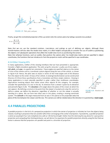
Consider a flight-simulation application. The pilot using the simulator usually uses three angles—
roll, pitch, and yaw—to specify her orientation. These angles are specified relative to the center
of mass of the vehicle and to a coordinate system aligned along the axes of the vehicle, as shown
in Figure 4.19. Hence, the pilot sees an object in terms of the three angles and of the distance
from the object to the center of mass of her vehicle. A viewing transformation can be constructed
(Exercise 4.2) from these specifications from a translation and three simple rotations. Viewing in
many applications is most naturally specified in polar—rather than rectilinear—coordinates.
Applications involving objects that rotate about other objects fit this category. For example,
consider the specification of a star in the sky. Its direction from a viewer is given by its elevation
and azimuth (Figure 4.20). The elevation is the angle above the plane of the viewer at which the
star appears. By defining a normal at the point that the viewer is located and using this normal to
define a plane, we define the elevation, regardless of whether or not the viewer is actually
standing on a plane. We can form two other axes in this plane, creating a viewing-coordinate
system. The azimuth is the angle measured from an axis in this plane to the projection onto the
plane of the line between the viewer and the star. The camera can still be rotated about the direction it is pointed by a twist angle.
4.4 PARALLEL PROJECTIONS
A parallel projection is the limit of a perspective projection in which the center of projection is infinitely far from the objects being
viewed, resulting in projectors that are parallel rather than converging at the center of projection. Equivalently, a parallel projection
is what we would get if we had a telephoto lens with an infinite focal length. Rather than first deriving the equations for a perspective
projection and computing their limiting behavior, we will derive the equations for parallel projections directly using the fact that we
know in advance that the projectors are parallel and point in a direction of projection.
157