
Page 152 - Computer Graphics Handout
P. 152
In Chapters 2 and 3, we were able to show simple three-dimensional examples by using an identity matrix as the default projection
matrix. That default setting has the effect of creating an orthographic projection with the camera at the origin, pointed in the
negative z-direction. In our cube example in Chapter 3, we rotated the cube to see the desired faces. As we just discussed, rotating
the cube is equivalent to rotating the frame of the cube with respect to the frame of the camera; we could have achieved the same
view by rotating the camera relative to the cube.We can extend this strategy of translating and rotating the camera to create other
orthographic views. Perspective views require changes to the default projection.
Consider creating an isometric view of the cube. Suppose that again we start with a cube centered at the origin and aligned with
the axes. Because the default camera is in the middle of the cube, we want to move the camera away from the cube by a translation.
We obtain an isometric view when the camera is located symmetrically with respect to three adjacent faces of the cube; for example,
anywhere along the line from the origin through the point (1, 1, 1). We can move the cube away from the camera and then rotate
the cube to achieve the desired view or, equivalently, move the camera away from the cube and then rotate it to point at the cube.
Starting with the default camera, suppose that we are now looking at the cube from somewhere on the positive z-axis. We can
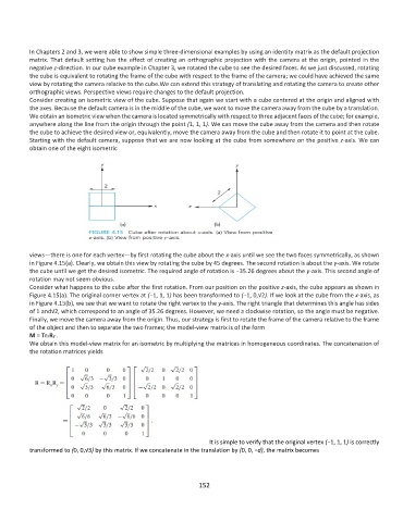
obtain one of the eight isometric
views—there is one for each vertex—by first rotating the cube about the x-axis until we see the two faces symmetrically, as shown
in Figure 4.15(a). Clearly, we obtain this view by rotating the cube by 45 degrees. The second rotation is about the y-axis. We rotate
the cube until we get the desired isometric. The required angle of rotation is −35.26 degrees about the y-axis. This second angle of
rotation may not seem obvious.
Consider what happens to the cube after the first rotation. From our position on the positive z-axis, the cube appears as shown in
Figure 4.15(a). The original corner vertex at (−1, 1, 1) has been transformed to (−1, 0,√2). If we look at the cube from the x-axis, as
in Figure 4.15(b), we see that we want to rotate the right vertex to the y-axis. The right triangle that determines this angle has sides
of 1 and√2, which correspond to an angle of 35.26 degrees. However, we need a clockwise rotation, so the angle must be negative.
Finally, we move the camera away from the origin. Thus, our strategy is first to rotate the frame of the camera relative to the frame
of the object and then to separate the two frames; the model-view matrix is of the form
M = TrxRy .
We obtain this model-view matrix for an isometric by multiplying the matrices in homogeneous coordinates. The concatenation of
the rotation matrices yields
It is simple to verify that the original vertex (−1, 1, 1) is correctly
transformed to (0, 0,√3) by this matrix. If we concatenate in the translation by (0, 0, −d), the matrix becomes
152