
Page 149 - Computer Graphics Handout
P. 149
to be visible to lie within the clipping cube in clip coordinates. The camera was fixed to be at the origin and pointing in the negative
26
z-direction in clip coordinates . To get a more flexible way to do viewing, we will separate the process into two fundamental
operations.
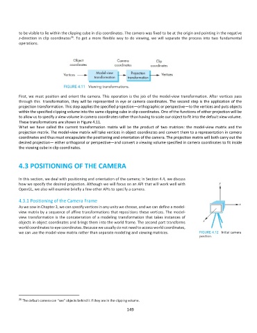
First, we must position and orient the camera. This operation is the job of the model-view transformation. After vertices pass
through this transformation, they will be represented in eye or camera coordinates. The second step is the application of the
projection transformation. This step applies the specified projection—orthographic or perspective—to the vertices and puts objects
within the specified clipping volume into the same clipping cube in clip coordinates. One of the functions of either projection will be
to allow us to specify a view volume in camera coordinates rather than having to scale our object to fit into the default view volume.
These transformations are shown in Figure 4.11.
What we have called the current transformation matrix will be the product of two matrices: the model-view matrix and the
projection matrix. The model-view matrix will take vertices in object coordinates and convert them to a representation in camera
coordinates and thus must encapsulate the positioning and orientation of the camera. The projection matrix will both carry out the
desired projection— either orthogonal or perspective—and convert a viewing volume specified in camera coordinates to fit inside
the viewing cube in clip coordinates.
4.3 POSITIONING OF THE CAMERA
In this section, we deal with positioning and orientation of the camera; in Section 4.4, we discuss
how we specify the desired projection. Although we will focus on an API that will work well with
OpenGL, we also will examine briefly a few other APIs to specify a camera.
4.3.1 Positioning of the Camera Frame
As we saw in Chapter 3, we can specify vertices in any units we choose, and we can define a model-
view matrix by a sequence of affine transformations that repositions these vertices. The model-
view transformation is the concatenation of a modeling transformation that takes instances of
objects in object coordinates and brings them into the world frame. The second part transforms
world coordinates to eye coordinates. Because we usually do not need to access world coordinates,
we can use the model-view matrix rather than separate modeling and viewing matrices.
26 The default camera can “see” objects behind it if they are in the clipping volume.
149