
Page 154 - Computer Graphics Handout
P. 154
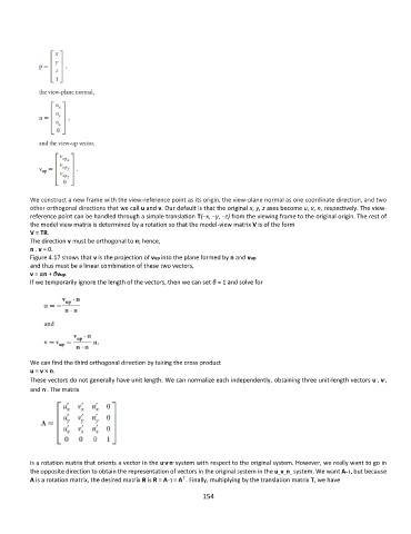
We construct a new frame with the view-reference point as its origin, the view-plane normal as one coordinate direction, and two
          other orthogonal directions that we call u and v. Our default is that the original x, y, z axes become u, v, n, respectively. The view-
          reference point can be handled through a simple translation T(−x, −y, −z) from the viewing frame to the original origin. The rest of
          the model view matrix is determined by a rotation so that the model-view matrix V is of the form
          V = TR.
          The direction v must be orthogonal to n; hence,
          n . v = 0.
          Figure 4.17 shows that v is the projection of vup into the plane formed by n and vup
          and thus must be a linear combination of these two vectors,
          v = αn + βvup.
          If we temporarily ignore the length of the vectors, then we can set β = 1 and solve for


          We can find the third orthogonal direction by taking the cross product
          u = v × n.
                                                                                                                   ,
                                                                                                                 ,
          These vectors do not generally have unit length. We can normalize each independently, obtaining three unit-length vectors u , v ,
               ,
          and n . The matrix


                                                  , , ,
          is a rotation matrix that orients a vector in the u v n system with respect to the original system. However, we really want to go in
          the opposite direction to obtain the representation of vectors in the original system in the u_v_n_ system. We want A−1, but because
                                                       T
          A is a rotation matrix, the desired matrix R is R = A−1 = A . Finally, multiplying by the translation matrix T, we have
                                                             154