
Page 153 - Computer Graphics Handout
P. 153
In OpenGL, the code for setting the model-view matrix is as follows:
mat4 model_view;
model_view = Translate(0.0, 0.0, -d)*RotateX(35.26)*RotateY(45.0);
We have gone from a representation of our objects in object coordinates to one in camera coordinates. Rotation and translation do
not affect the size of an object nor, equivalently, the size of its orthographic projection. However, these transformations can affect
whether or not objects are clipped. Because the clipping volume is measured relative to the camera, if, for example, we translate
the object away from the camera, it may no longer lie within the clipping volume. Hence, even though the projection of the object
is unchanged and the camera still points at it, the object would not be in the image.
4.3.2 Two Viewing APIs
The construction of the model-view matrix for an isometric view is a little unsatisfying. Although the approach was intuitive, an
interface that requires us to compute the individual angles before specifying the transformations is a poor one for an application
program. We can take a different approach to positioning the camera—an approach that is similar to
that used by PHIGS, one of the original standard APIs for three-dimensional graphics. Our starting
point is again the object frame.We describe the camera’s position and orientation in this frame. The
precise type of image that we wish to obtain—perspective or parallel—is determined separately by
the specification of the projection matrix. This second part of the viewing process is often called the
normalization transformation.We approach this problem as one of a change in frames. Again, we
think of the camera as positioned initially at the origin, pointed in the negative z-direction. Its desired
location is centered at a point called the viewreference point (VRP; Figure 4.16), whose position is
given in the object frame. The user executes a function such as
set_view_reference_point(x, y, z);
to specify this position. Next, we want to specify the orientation of the camera. We can divide this
specification into two parts: specification of the view-plane normal (VPN) and specification of the
view-up vector (VUP). The VPN (n in Figure 4.16) gives the orientation of the projection plane or back of the camera. The orientation
of a plane is determined by that plane’s normal, and thus part of the API is a function such as
set_view_plane_normal(nx, ny, nz);
The orientation of the plane does not specify what direction is up from the camera’s perspective. Given only the VPN, we can rotate
the camera with its back in this plane.
The specification of the VUP fixes the camera and is performed by a function such as
set_view_up(vup_x, vup_y, vup_z);
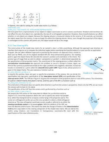
We project the VUP vector on the view plane to obtain the up-direction vector v
(Figure 4.17). Use of the projection allows the user to specify any vector not parallel
to v, rather than being forced to compute a vector lying in the projection plane. The
vector v is orthogonal to n.We can use the cross product to obtain a third orthogonal
direction u. This new orthogonal coordinate system usually is referred to as either the
viewing-coordinate system or the u-v-n system. With the addition of the VRP, we
have the desired camera frame. The matrix that does the change of frames is the vieworientation
matrix and is equivalent to the viewing component of the model-view matrix. We can derive this
matrix using rotations and translations in homogeneous coordinates.We start with the
specifications of the view-reference point,
153