
Page 155 - Computer Graphics Handout
P. 155
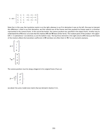
Note that, in this case, the translation matrix is on the right, whereas in our first derivation it was on the left. One way to interpret
          this difference is that in our first derivation, we first rotated one of the frames and then pushed the frames apart in a direction
          represented in the camera frame. In the second derivation, the camera position was specified in the object frame. Another way to
          understand this difference is to note that the matrices RT and TR have similar forms. The rotation parts of the product—the upper-
          left 3 × 3 submatrices—are identical, as are the bottom rows. The top three elements in the right column differ because the frame
          of the rotation affects the translation coefficients in RT and does not affect them in TR. For our isometric example,


          The camera position must be along a diagonal in the original frame. If we use


          we obtain the same model-view matrix that we derived in Section 4.3.1.


                                                             155