
Page 161 - Computer Graphics Handout
P. 161
near and far distances in Ortho is that they determine which objects are clipped out. Now suppose that, instead, we set the Ortho
parameters by the following function call:
mat4 N = Ortho(left, right, bottom, top, near, far);
We now have specified a right parallelepiped view volume whose right side (relative to the camera) is the plane x = left, whose left
side is the plane x = right, whose top is the plane y = top, and whose bottom is the plane y = bottom. The front is the near clipping
plane z =−near, and the back is the far clipping plane z =−far. The projection matrix that OpenGL sets up is the matrix that transforms
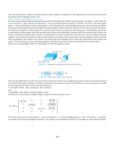
this volume to the cube centered at the origin with sides of length 2, which is shown in Figure 4.25. This matrix converts the vertices
that specify our objects to vertices within this canonical view volume, by scaling and translating them. Consequently, vertices are
transformed such that vertices within the specified view volume are transformed to vertices within the canonical view volume, and
vertices outside the specified view volume are transformed to vertices outside the canonical view volume. Putting everything
together, we see that the projection matrix is determined by the type of view and the view volume specified in Ortho, and that
these specifications are relative to the camera. The positioning and orientation of the camera are determined by the model-view
matrix. These two matrices are concatenated together, and objects have their vertices transformed by this matrix product.
We can use our knowledge of affine transformations to find this projection matrix.
There are two tasks that we need to do. First, we must move the center of the specified view volume to the center of the canonical
view volume (the origin) by doing a translation. Second, we must scale the sides of the specified view volume to each have a length
of 2 (see Figure 4.25). Hence, the two transformations are
T = T(−(right + left)/2, −(top + bottom)/2, +(far + near)/2)
and
S = S(2/(right – left), 2/(top – bottom), 2/(near – far)),
and they can be concatenated together (Figure 4.26) to form the projection matrix
This matrix maps the near clipping plane, z =−near, to the plane z =−1 and the far clipping plane, z =−far , to the plane z = 1. Because
the camera is pointing in the negative z-direction, the projectors are directed from infinity on the negative z-axis toward the origin.
161