
Page 177 - Computer Graphics Handout
P. 177
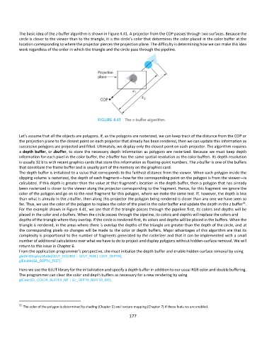
The basic idea of the z-buffer algorithm is shown in Figure 4.41. A projector from the COP passes through two surfaces. Because the
          circle is closer to the viewer than to the triangle, it is the circle’s color that determines the color placed in the color buffer at the
          location corresponding to where the projector pierces the projection plane. The difficulty is determining how we can make this idea
          work regardless of the order in which the triangle and the circle pass through the pipeline.


          Let’s assume that all the objects are polygons. If, as the polygons are rasterized, we can keep track of the distance from the COP or
          the projection plane to the closest point on each projector that already has been rendered, then we can update this information as
          successive polygons are projected and filled. Ultimately, we display only the closest point on each projector. The algorithm requires
          a depth buffer, or zbuffer, to store the necessary depth information as polygons are rasterized. Because we must keep depth
          information for each pixel in the color buffer, the z-buffer has the same spatial resolution as the color buffers. Its depth resolution
          is usually 32 bits with recent graphics cards that store this information as floating-point numbers. The z-buffer is one of the buffers
          that constitute the frame buffer and is usually part of the memory on the graphics card.
          The depth buffer is initialized to a value that corresponds to the farthest distance from the viewer. When each polygon inside the
          clipping volume is rasterized, the depth of each fragment—how far the corresponding point on the polygon is from the viewer—is
          calculated. If this depth is greater than the value at that fragment’s location in the depth buffer, then a polygon that has already
          been rasterized is closer to the viewer along the projector corresponding to the fragment. Hence, for this fragment we ignore the
          color of the polygon and go on to the next fragment for this polygon, where we make the same test. If, however, the depth is less
          than what is already in the z-buffer, then along this projector the polygon being rendered is closer than any one we have seen so
                                                                                                                  31
          far. Thus, we use the color of the polygon to replace the color of the pixel in the color buffer and update the depth in the z buffer .
          For the example shown in Figure 4.41, we see that if the triangle passes through the pipeline first, its colors and depths will be
          placed in the color and z-buffers. When the circle passes through the pipeline, its colors and depths will replace the colors and
          depths of the triangle where they overlap. If the circle is rendered first, its colors and depths will be placed in the buffers. When the
          triangle is rendered, in the areas where there is overlap the depths of the triangle are greater than the depth of the circle, and at
          the corresponding pixels no changes will be made to the color or depth buffers. Major advantages of this algorithm are that its
          complexity is proportional to the number of fragments generated by the rasterizer and that it can be implemented with a small
          number of additional calculations over what we have to do to project and display polygons without hidden-surface removal. We will
          return to this issue in Chapter 6.
          From the application programmer’s perspective, she must initialize the depth buffer and enable hidden-surface removal by using
          glutInitDisplayMode(GLUT_DOUBLE | GLUT_RGB | GLUT_DEPTH);
          glEnable(GL_DEPTH_TEST);
          Here we use the GLUT library for the initialization and specify a depth buffer in addition to our usual RGB color and double buffering.
          The programmer can clear the color and depth buffers as necessary for a new rendering by using
          glClear(GL_COLOR_BUFFER_BIT | GL_DEPTH_BUFFER_BIT);


          31  The color of the polygon is determined by shading (Chapter 5) and texture mapping (Chapter 7) if these features are enabled.

                                                             177