
Page 47 - Computer Graphics Handout
P. 47
At some point, the values in vertex coordinates must be mapped to window coordinates, as shown in Figure 2.5. The graphics
system, rather than the user, is responsible for this task, and the mapping is performed automatically as part of the rendering
process. As we will see in the next few sections, to define this mapping the user needs to specify only a few parameters—such as
the area of the world that she would like to see and the size of the display. However, between the application and the frame buffer
are the two shaders and rasterizer, and, as we shall see when we discuss viewing, there are three other intermediate coordinate
systems of importance.
2.4 PRIMITIVES AND ATTRIBUTES
Within the graphics community, there has been an ongoing debate about which primitives should be supported in an API. The
debate is an old one and has never been fully resolved. On the minimalist side, the contention is that an API should contain a small
set of primitives that all hardware can be expected to support. In addition, the primitives should be orthogonal, each giving a
capability unobtainable from the others. Minimal systems typically support lines, polygons, and some form of text (strings of
characters), all of which can be generated efficiently in hardware. On the other end are systems that can also support a variety of
primitives, such as circles, curves, surfaces, and solids. The argument here is that users need more complex primitives to build
sophisticated applications easily. However, because few hardware systems can be expected to support the large set of primitives
that is the union of all the desires of the user community, a program developed with such a system probably would not be portable,
because few implementations could be expected to support the entire set of primitives.
As graphics hardware has improved and real-time performance has become measured in the tens of millions of polygons per second,
the balance has tilted toward supporting a minimum set of primitives. One reason is that GPUs achieve their speed largely because
they are optimized for points, lines, and triangles. We will develop code later that will approximate various curves and surfaces with
primitives that are supported on GPUs.
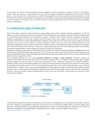
We can separate primitives into two classes: geometric primitives and image, or raster, primitives. Geometric primitives are
specified in the problem domain and include points, line segments, polygons, curves, and surfaces. These primitives pass through a
geometric pipeline, as shown in Figure 2.6, where they are subject to a series of geometric operations that determine whether a
primitive is visible, where on the display it appears if it is visible, and the rasterization of the primitive into pixels in the frame buffer.
Because geometric primitives exist in a two- or three-dimensional space, they can be manipulated by operations such as rotation
and translation. In addition, they can be used as building blocks for other geometric objects using these same operations. Raster
primitives, such as arrays of pixels, lack geometric properties and cannot be manipulated in space in the same way as geometric
primitives. They pass through a separate parallel pipeline on their way to the frame buffer. We will defer our discussion of raster
primitives until Chapter 7.
The basic OpenGL geometric primitives are specified by sets of vertices. An application starts by computing vertex data—positions
and other attributes—and putting the results into arrays that are sent to the GPU for display. When we want to display some
geometry, we execute functions whose parameters specify how the vertices are to be interpreted. For example, we can display the
vertices we computed for the Sierpinski gasket, starting with the first vertex, as points through the function call
glDrawArrays(GL_POINTS, 0, NumPoints);
47