
Page 46 - Computer Graphics Handout
P. 46
where the * can be interpreted as either two or three characters of the formnt or ntv, where n signifies the number of dimensions
(2, 3, 4, or matrix); t denotes the data type, such as integer (i), float (f), or double (d); and v, if present, indicates that the variables
are specified through a pointer to an array, rather than through an argument list. We will use whatever form is best suited for our
discussion, leaving the details
of the various other forms to the OpenGL Programming Guide [Shr10]. Regardless of which form an application programmer
chooses, the underlying representation is the same, just as the plane on which we are constructing the gasket can be looked at as
either a two-dimensional space or the subspace of a three-dimensional space corresponding to the plane z = 0. In Chapter 3, we will
see that the underlying representation is four-dimensional; however, we do not need to worry about that fact yet. In general, the
application programmer chooses the form to use that is best suited for her application.
2.3.4 Coordinate Systems
At this point, if we look back at our Sierpinski gasket code, youmay be puzzled about how to interpret the values of x, y, and z in our
specification of vertices. In what units are they? Are they in feet, meters, microns? Where is the origin? In each case, the simple
answer is that it is up to you. Originally, graphics systems required the user to specify all information, such as vertex locations,
directly in units of the display device. If that were true for high-level application programs, we would have to talk about points in
terms of screen locations in pixels or centimeters froma corner of the display. There are obvious problems with this method, not
the least of which is the absurdity of using distances on the computer screen to describe phenomena where the natural unit might
be light years (such as in displaying astronomical data) or microns (for integrated-circuit design). One of the major advances in
graphics software systems occurred when the graphics systems allowed users to work in any coordinate system that they desired.
The advent of device-independent graphics freed application programmers from worrying about the details of input and output
devices. The user’s coordinate system became known as the world coordinate system, or the application or object coordinate
system.
Within the slight limitations of floating-point arithmetic on our computers, we can use any numbers that fit our application. We will
refer to the units that the application programuses to specify vertex positions as vertex coordinates. In most applications, vertex
coordinates will be the same as object or world coordinates, but depending on what we choose to do or not do in our shaders,
vertex coordinates can be one of the other internal coordinate systems used in the pipeline. We will discuss these other coordinate
systems in Chapters 3 and 4.
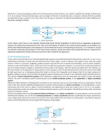
Units on the display were first called physical-device coordinates or just device coordinates. For raster devices, such as most CRT
and flat panel displays, we use the termwindowcoordinates or screen coordinates.Window coordinates are always expressed in
some integer type, because the center of any pixel in the frame buffer must be located on a fixed grid or, equivalently, because
pixels are inherently discrete and we specify their locations using integers.
46