
Page 27 - GuardII+ Series 4208 Platform PD User Manual
P. 27
PD Card Operation
4.6.8. Polarity Predominance Triggers
These Triggers detect a significant predominance of either positive or negative PD and
resolve down to a combination of input pair, sensor and polarity. This means that positive
predominance detected on input Phase A Machine PD causes a different Trigger than
negative predominance detected on input Phase A Machine PD; each combination of input,
sensor and polarity has its own Trigger.
The Trigger interval for is 30 days; additionally, the current PD levels must be higher than
the Moderate Threshold setting, and the Trigger must be confirmed over multiple
measurement cycles before the Trigger actually occurs.
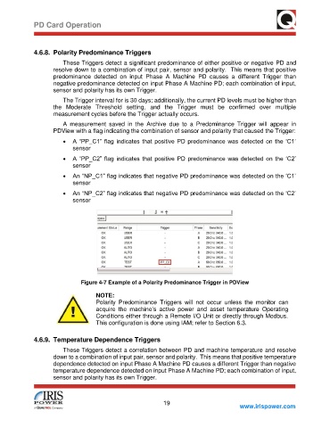
A measurement saved in the Archive due to a Predominance Trigger will appear in
PDView with a flag indicating the combination of sensor and polarity that caused the Trigger:
• A “PP_C1” flag indicates that positive PD predominance was detected on the ‘C1’
sensor
• A “PP_C2” flag indicates that positive PD predominance was detected on the ‘C2’
sensor
• An “NP_C1” flag indicates that negative PD predominance was detected on the ‘C1’
sensor
• An “NP_C2” flag indicates that negative PD predominance was detected on the ‘C2’
sensor
Figure 4-7 Example of a Polarity Predominance Trigger in PDView
NOTE:
Polarity Predominance Triggers will not occur unless the monitor can
acquire the machine’s active power and asset temperature Operating
Conditions either through a Remote I/O Unit or directly through Modbus.
This configuration is done using IAM; refer to Section 6.3.
4.6.9. Temperature Dependence Triggers
These Triggers detect a correlation between PD and machine temperature and resolve
down to a combination of input pair, sensor and polarity. This means that positive temperature
dependence detected on input Phase A Machine PD causes a different Trigger than negative
temperature dependence detected on input Phase A Machine PD; each combination of input,
sensor and polarity has its own Trigger.
19
www.irispower.com