
Page 78 - GuardII+ Series 4208 Platform PD User Manual
P. 78
Troubleshooting
whether the hardware has been properly detected or whether the system is configured
properly. For rapid resolution of any Technical Support issue, this should be included on any
Technical Support inquiry.
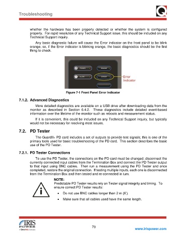
Any basic diagnostic failure will cause the Error indicator on the front panel to be blink
orange; so, if the Error indicator is blinking orange, the basic diagnostics should be the first
thing to check.
Figure 7-1 Front Panel Error Indicator
7.1.2. Advanced Diagnostics
More detailed diagnostics are available on a USB drive after downloading data from the
monitor as described in Section 6.4.2. These diagnostics include detailed event-based
information over the lifetime of the monitor such as reboots and measurement status.
If it is convenient, this could be included on any Technical Support inquiry, but typically
would not be necessary for resolving most issues.
7.2. PD Tester
The GuardII+ PD card includes a set of outputs to provide test signals; this is one of the
primary tools used for basic troubleshooting of the PD card. This section describes the basic
use of the PD Tester.
7.2.1. PD Tester Connections
To use the PD Tester, the connections on the PD card must be changed; disconnect the
currently connected input cables from the Termination Box and connect the PD Tester output
to that input using BNC cables. Then run a measurement using the PD Tester and once
completed, restore the original connection. If testing multiple inputs, each one is disconnected
from the Termination Box and then tested and re-connected in turn.
NOTE:
Predictable PD Tester results rely on Tester signal integrity and timing. To
ensure correct PD Tester results:
• Do not use BNC cables longer than 2 m (6’).
• Make sure that all cables used have the same length.
70
www.irispower.com