
Page 80 - GuardII+ Series 4208 Platform PD User Manual
P. 80
Troubleshooting
7.2.2. PD Tester Setup
To actually run a measurement using the PD Tester, use IAM to perform a single-shot
measurement as described in Section 6.6 with the appropriate connections. Configuration
changes may be needed, since the PD Tester requires a specific measurement setup to
produce the correct results:
PD Type Parameter Setting
10 mV – 170 mV OR
Sensitivity
100 mV – 1700 mV
BUS Delay 6 ns
Sync Source Sensor
Phase Adjustment 90
10 mV – 170 mV OR
Sensitivity 100 mV – 1700 mV
PDA
Sync Source Sensor
Phase Adjustment 90
10 mV – 170 mV OR
Sensitivity 100 mV – 1700 mV
SSC
Sync Source External (100 mV ~ 48 Vac)
Phase Adjustment 0
Note that the PD Tester is set to run at either 60 Hz or 50 Hz depending on the Operating
frequency of the asset. To make sure that the PD Tester measurements will succeed, the
GuardII+ Line Frequency must be set to either 50 Hz or 60 Hz.
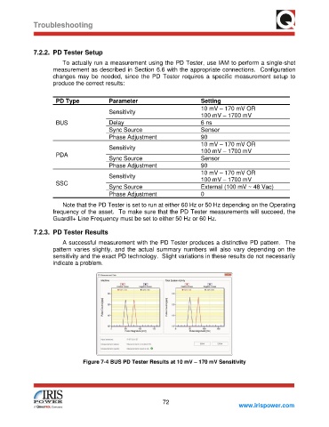
7.2.3. PD Tester Results
A successful measurement with the PD Tester produces a distinctive PD pattern. The
pattern varies slightly, and the actual summary numbers will also vary depending on the
sensitivity and the exact PD technology. Slight variations in these results do not necessarily
indicate a problem.
Figure 7-4 BUS PD Tester Results at 10 mV – 170 mV Sensitivity
72
www.irispower.com