
Page 1138 - 2006 HARLEY FLSTCI SERVICE MANUAL
P. 1138
9-11
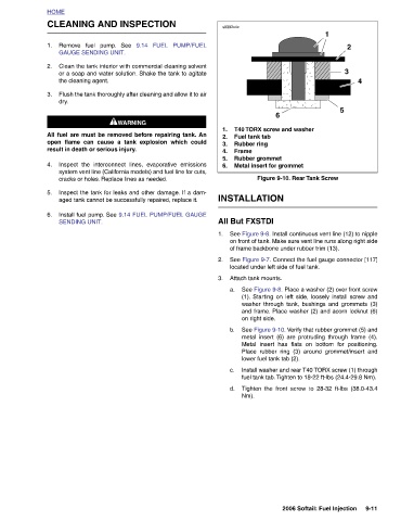
4
2
3
5
1 See Figure 9-8. Install continuous vent line (12) to nipple on front of tank. Make sure vent line runs along right side See Figure 9-7. Connect the fuel gauge connector [117] a. See Figure 9-8. Place a washer (2) over front screw (1). Starting on left side, loosely install screw and washer through tank, bushings and grommets (3) and frame. Place washer (2) and acorn locknut (6) See Figure 9-10. Verify that rubber grommet (5) and metal insert (6) are protruding through frame (4). Metal insert has flats on bottom for positioning. Place rubber ring (3) around grommet/insert and Install wash
T40 TORX screw and washer Rubber grommet Metal insert for grommet located under left side of fuel tank. Attach tank mounts. on right side. lower fuel tank tab (2).
6 Figure 9-10. Rear Tank Screw of frame backbone under rubber trim (13).
s0392x4x 1. Fuel tank tab 2. Rubber ring 3. Frame 4. 5. 6. INSTALLATION All But FXSTDI 1. 2. 3. b. c. d. Nm).
9.14 FUEL PUMP/FUEL
CLEANING AND INSPECTION
Clean the tank interior with commercial cleaning solvent or a soap and water solution. Shake the tank to agitate Flush the tank thoroughly after cleaning and allow it to air Inspect the interconnect lines, evaporative emissions system vent line (California models) and fuel line for cuts, Inspect the tank for leaks and other damage. If a dam- Install fuel pump. See 9.14 FUEL PUMP/FUEL GAUGE
Remove fuel pump. See GAUGE SENDING UNIT. the cleaning agent. 1WARNING 1WARNING All fuel are must be removed before repairing tank. An open flame can cause a tank explosion which could result in death or serious injury. cracks or holes. Replace lines as needed. aged tank cannot be successfully repaired, replace it. SENDING UNIT.
HOME 1. 2. 3. dry. 4. 5. 6.