
Page 1141 - 2006 HARLEY FLSTCI SERVICE MANUAL
P. 1141
9.7 4
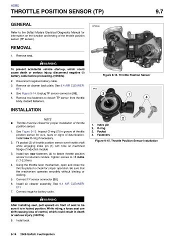
Figure 9-14. Throttle Position Sensor 1 2 Figure 9-15. Throttle Position Sensor Installation
THROTTLE POSITION SENSOR (TP)
d0766x9x 9472 3 Index pin 1. O-ring 2. Pocket 3. Fasteners 4.
information on the function and testing of the throttle position
Refer to the Softail Models Electrical Diagnostic Manual for
9.4 AIR CLEANER:
1WARNING 1WARNING prevent accidental vehicle start-up, which could cause death or serious injury, disconnect negative (-) battery cable before proceeding. (00048a) Disconnect negative battery cable. Remove air cleaner back plate. See 9.4 AIR CLEANER: See Figure 9-14. Unplug TP sensor connector [88]. Remove two fasteners to detach TP sensor from throttle NOTE Throttle must be closed for proper installation of throttle See Figure 9-15. Inspect O-ring (2) in groove of throttle position sensor for cuts, tears or signs of deterioration. Install new O-ring if necessary. Fit pocket (3) of throttle position sensor over thr
GENERAL sensor (TP sensor). REMOVAL Remove seat. EFI. body. discard fasteners. INSTALLATION position sensor. flange of induction module (1.7-2.3 Nm) sticking. EFI. or serious injury. (00070a) Install seat.
HOME 1. To 2. 3. 4. 5. ● 1. 2. 3. 4. 5. 6. 7. 8. 9-14