
Page 1140 - 2006 HARLEY FLSTCI SERVICE MANUAL
P. 1140
9.6 9-13
2 2
2
2 2006 Softail: Fuel Injection
2
2
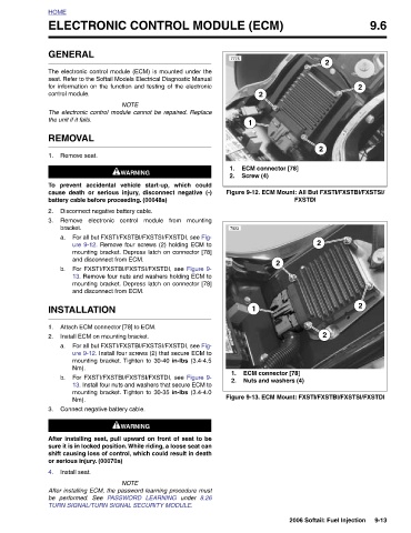
FXSTDI Figure 9-12. ECM Mount: All But FXSTI/FXSTBI/FXSTSI/ Figure 9-13. ECM Mount: FXSTI/FXSTBI/FXSTSI/FXSTDI
ECM connector [78] 2 ECM connector [78] Nuts and washers (4)
ELECTRONIC CONTROL MODULE (ECM)
2
1 Screw (4) 1
7775 1. 2. 7923 1. 2.
8.26
seat. Refer to the Softail Models Electrical Diagnostic Manual
The electronic control module (ECM) is mounted under the
for information on the function and testing of the electronic
under
1WARNING 1WARNING prevent accidental vehicle start-up, which could Remove electronic control module from mounting For all but FXSTI/FXSTBI/FXSTSI/FXSTDI, see Fig- ure 9-12. Remove four screws (2) holding ECM to mounting bracket. Depress latch on connector [78] For FXSTI/FXSTBI/FXSTSI/FXSTDI, see Figure 9- 13. Remove four nuts and washers holding ECM to mounting bracket. Depress latch on connector [78] For all but FXSTI/FXSTBI/FXSTSI/FXSTDI, see Fig- ure 9-12. Install four screws (2) that secure ECM to mounting bracket. Tighten to 30-40 in-lbs (3.4-4.5 For FXSTI/FXSTBI/FXSTSI/FXSTDI, see Figure 9- 13.
NOTE The electronic control module cannot be repaired. Replace cause death or serious injury, disconnect negative (-) battery cable before proceeding. (00048a) Disconnect negative battery cable. and disconnect from ECM. and disconnect from ECM. Attach ECM connector [78] to ECM. Install ECM on mounting bracket. Connect negative battery cable. After installing seat, pull upward on front of seat to be sure it is in locked position. While riding, a loose seat can shift causing loss of control, which could result in death NOTE After installing ECM, the password learning procedure must TURN SIGNAL/TURN SIGNAL SECURITY MODULE.
GENERAL control module. the unit if it fails. REMOVAL Remove seat. bracket. INSTALLATION Nm). Nm). or serious injury. (00070a) Install seat. be performed. See
HOME 1. To 2. 3. a. b. 1. 2. a. b. 3. 4.