
Page 1216 - 2006 HARLEY FLSTCI SERVICE MANUAL
P. 1216
Before proceeding with the disassembly procedure,
source. If light is visible around edges of seats, then
Raise valve ports of cylinder head to strong light
3.5 3-5
determine if cylinder head reconditioning is necessary.
move to step 2 to recondition cylinder head. Fill ports at top of cylinder head with solvent. Wait ten full seconds and then check for leakage into combustion chamber. If solvent leakage into com- bustion chamber is evident, then move to step 2 to recondition cylinder head. See Figure 3-4. Secure cylinder head for service. Thread 12 mm end of CYLINDER HEAD HOLDING FIXTURE (1) (Part No. HD-39786-A) into cylinder head (2) spark plug hole. Clamp tool in vise at a 45 degree angle or one that offers a comfortable working position. See Figure 3-5. Release valve spring compression. Place VALVE SPRING COMPRESSOR (2) (Part No. HD-34736-B) o
a. b. a. b. a. b. See c. d. compression. (4) valve springs.
1. 2. 3. 4. 5. 6. 7. 8. 9. 10.
The 2006 Softail 2 SPECIALTY TOOL
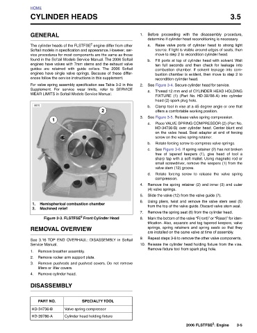
CYLINDER HEADS The cylinder heads of the FLSTFSE 2 engine differ from other Softail models in specification and appearance. However, ser- vice procedures for most components are the same as those found in the Softail Models Service Manual. The 2006 Softail engines have valves with 7mm stems and the exhaust valve guides are retained with guide collars. engines have single valve springs. Because of these differ- ences follow the service instructions in this supplement. For valve spring assembly specification see Table 3-2 in this Supplement. For service wear limits, refer to SERVICE WEAR LIMITS in Softail Models Service Manual. 1 Hemispherical combu
HOME GENERAL 9975 1. 2. Service Manual. 1. 2. 3. 4. PART NO. HD-34736-B HD-39786-A