
Page 1220 - 2006 HARLEY FLSTCI SERVICE MANUAL
P. 1220
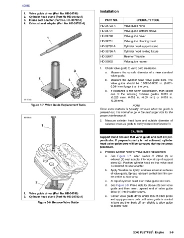
SPECIALTY TOOL      Cylinder head holding fixture  Measure the outside diameter of a  new  standard Measure the cylinder head valve guide bore. The valve guide should be 0.0020-0.0033 in. (0.051- If clearance is not within specification, then select one of the following oversize guides: 0.001 in. (0.025 mm), 0.002 in. (0.05 mm) or 0.003 in.  Insert sleeve of intake (3) or exhaust (4) seat adapter into tube at top of support stand (2). Position cylinder head so that valve seat Apply Vaseline to lightly lubricate external surfaces of valve guide. Spread lubricant so that thin film cov-  guide and then insert tapered end of valve guide Center valve gu


                      Valve guide hone  Valve guide installer sleeve  Valve guide driver  Valve guide cleaning brush  Cylinder head support stand  Reamer T-handle  Valve guide reamer Check valve guide to valve bore clearance.  0.084 mm) larger than the bore.   NOTE Since some material is typically removed when the guide is pressed out, it is normal to go to the next larger size for the Measure cylinder head bore and outside diameter of selected oversize guide to verify correct interference fit.   CAUTION Support stand ensures that valve guide and seat are per- pendicular. If perpendicularity is not achieved, cylinder head valve guide bore will be damaged during the


              Installation  PART NO.  HD-34723-A  HD-34731  HD-34740  HD-34751  HD-39782-A  HD-39786-A  HD-39847  HD-39932  1.  a.   valve guide.  b.   c.   (0.08 mm).  proper interference fit.  2.  procedure.  3.  a. See   b.   c.   e.   to center itself.


               Valve guide driver (Part No. HD-34740) Cylinder head stand (Part No HD-39782-A) Intake seat adapter (Part No. HD-39782-3) Exhaust seat adapter (Part No. HD-39782-4)  1  1  Valve guide driver (Part No. HD-34740) Cylinder head stand (Part No HD-39782-A)
                                                   3     4

                                                                         Figure 3-7. Valve Guide Replacement Tools                    Figure 3-8. Remove Valve Guide


          HOME  1.  2.  3.  4.                          2            d0167x3x   d0168x3x                                  2      1.  2.